44
54321
9876
4 Operation of the Unit
4.1 Operation Accessories
ANTRIEBSTECHNIK
START
STOP
FUNC.
SPEED
ENTER
F/R
ANTRIEBSTECHNIK
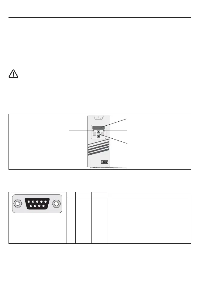
Double function keyboard
Operating / Error display
Normal "LED on"
Error "LED blinks"
Interface control
BUS-Operation "LED on"
(only 00.F5.060-2000)
5-digit LED display
RS232/RS485
(only 00.F5.060-2000)
4.1.1 With HSP5 cable and without operator
A special cable (Part no. 00.F5.0C0-0001) is necessary for the control of the KEB
COMBIVERT without operator. It is connected between the HSP5-interface X4A and a
serial RS232-PC-interface (COM1 or COM2). The operation takes place via the PC-pro-
gram COMBIVIS.
The HSP5-cable has an integrated level converter. The connection of a serial standard
cable would destroy the PC-interface.
4.1.2 Digital operator (Part no.: 00.F5.060-1000)
As an accessory for the local operation of the KEB COMBIVERT F5 an operator is available.
To prevent malfunctions, the inverter must be brought into
nOP
status before connecting /
disconnecting the operator (open control release terminal). When starting the inverter, it is
always started with the last stored values or the factory setting.
4.1.3 Interface operator (Part No.: 00.F5.060-2000)
The interface operator corresponds to the functional range of the digital operator. However,
it is enhanced by a serial RS232/485-interface.
A RS232-cable is needed to connect the interface operator with the PC. The assignment is
represented on the following page.
PIN RS485 Signal Meaning
1 – – reserved
2 – TxD Transmitter signal/RS232
3 – RxD Receiver signal/RS232
4 A' RxD-A Receiver signal A/RS485
5 B' RxD-B Receiver signal B/RS485
6 – VP Voltage supply - Plus +5V (I
max
= 10 mA)
7 C/C' DGND Data reference potential
8 A TxD-A Transmitter signal A/RS485
9 B TxD-B Transmitter signal B/RS485
Operation of the Unit
 Loading...


