CP 503/A, CP 505/A,D,K, CP 507/
A,C
Mounting and installation instructions
Project engineering manual V1.06
26
© KEBA 2021
5 Mounting and installation instructions
The CP 50x/x is intended for a horizontal installation on a mounting rail in a
control cabinet.
Additional modules (expansion modules and input/output modules) of the
KeConnect series can be arranged side-by-side on the module.
5.1 General instructions on assembly and removal
Caution
Switch off the operating and load voltage supplies before carrying out as-
sembly, installation or maintenance work.
5.2 Mounting rail
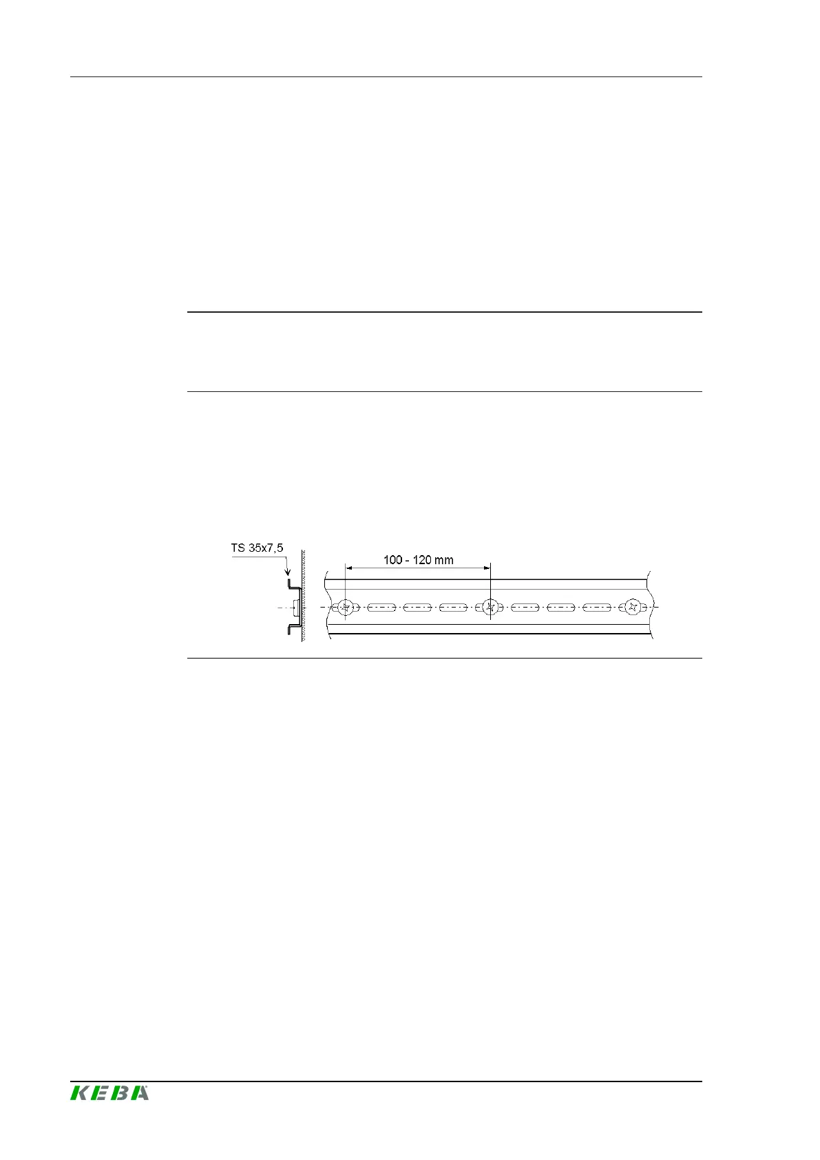
A steel rail TS 35x7.5 is to be used as mounting rail for the device. For the
sake of stability the screw distance, as shown in the illustration, must be be-
tween 100 - 120 mm.
Fig.5-10: Fixing of the mounting rail.
5.3 End bracket
To prevent the modules from slipping or loosening through vibration, an end
bracket must be mounted on the left and right side of the mounting rail. The
end bracket must be made of a non-conductive material to protect against
contact. Thus, the end bracket fulfills the function of a cover for existing con-
nectors.
 Loading...