CP 503/A, CP 505/A,D,K, CP 507/
A,C
Connections and wiring
Project engineering manual V1.06
52
© KEBA 2021
6.9 Graphic interface (DVI)
The DVI graphic interface (X60A DVI) is used to connect an operating panel.
The CP 50x/x has a standard DVI-D interface (digital signals only). A VGA
operation with adapter is not possible. The free pins are used for an RS485
retransfer (RFB interface).
Use the KEBA-supplied cable when connecting a KEBA operating device. A
standard operating device can be connected using a standard DVI cable. In
both cases, no damage to the device occurs despite the deviating pin as-
signment.
KEBA does not perform any tests for the correct functionality of operating
devices from third-party manufacturers.
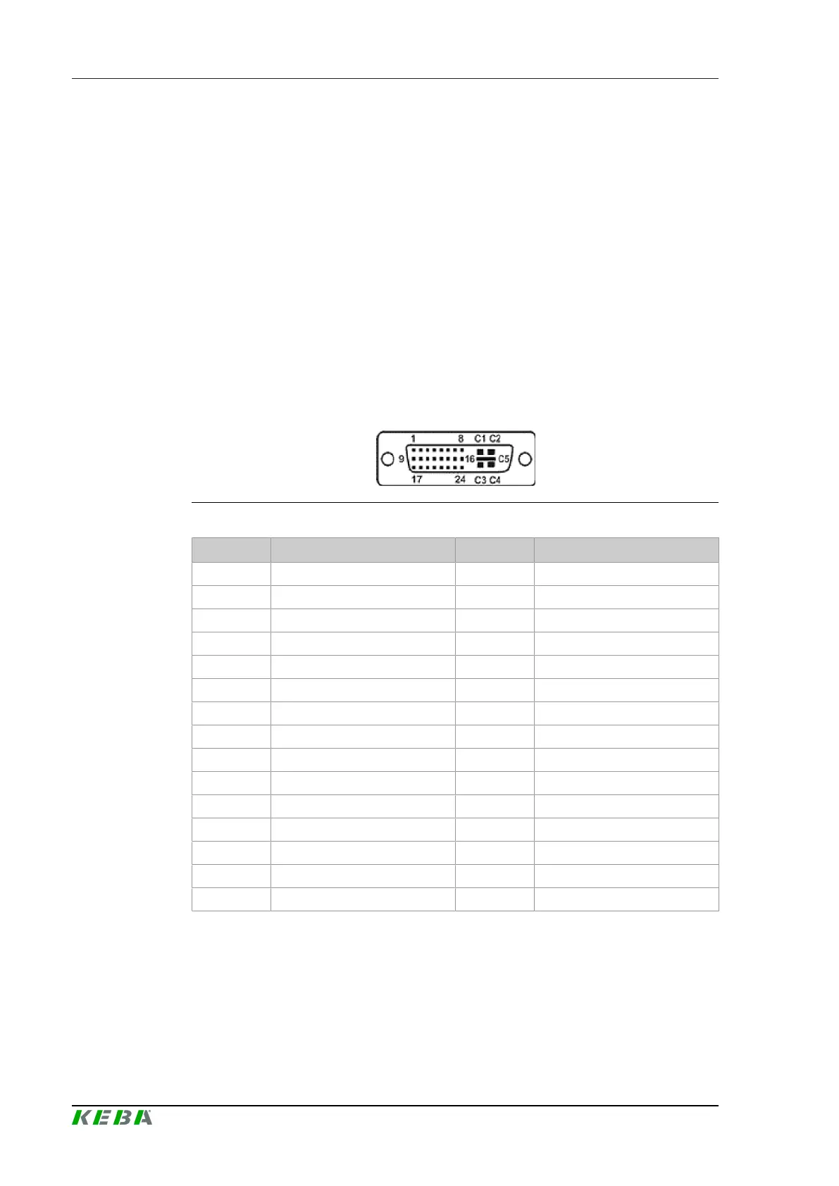
6.9.1 Pin assignment
Fig.6-41: Pin assignment DVI socket
Pin no. Designation Pin no. Designation
1 TDMS-Data 2- 2 TDMS-Data 2+
3 Shielding TDMS-Data 2,4 4 TDMS-Data 4-
5 TDMS-Data 4+ 6 DDC clock (SDC)
7 DDC data (SDA) 8 RS485 TX/RX+ *)
9 TDMS-Data 1- 10 TDMS-Data 1+
11 Shielding TDMS-Data 1,3 12 TDMS-Data 3-
13 TDMS-Data 3+ 14 +5 V
15 Ground for +5 V 16 Hotplug-Detect, enable RS485
17 TDMS-Data 0- 18 TDMS-Data 0+
19 Shielding TDMS 0,5 20 TDMS-Data 5-
21 TDMS-Data 5+ 22 Shielding TDMS-clock
23 TDMS-clock+ 24 TDMS-CLK-
C1 n.c. C2 n.c.
C3 n.c. C4 RS485 TX/RX- *)
C5 Analog: Ground → GND
*) Deviation to standard
6.9.2 Cable and plug specification
For details, refer to the system manual.
 Loading...