CP 503/A, CP 505/A,D,K, CP 507/
A,C
Configuration
Project engineering manual V1.06
54
© KEBA 2021
7 Configuration
A KEBA automation system requires data for the configuration of the system
behavior, its input and output devices and the interfaces. It reads those data
during startup and transmits them to the components and devices to be con-
figured. This configuration data is created with the supplied configuration tool
or by editing configuration files.
Please refer to the documentation of the supplied configuration tool for more
information on configuration.
7.1 CAN configuration
The termination of the CAN interface (CAN) is activated (ON) or deactivated
(OFF) via DIP switch (S1).
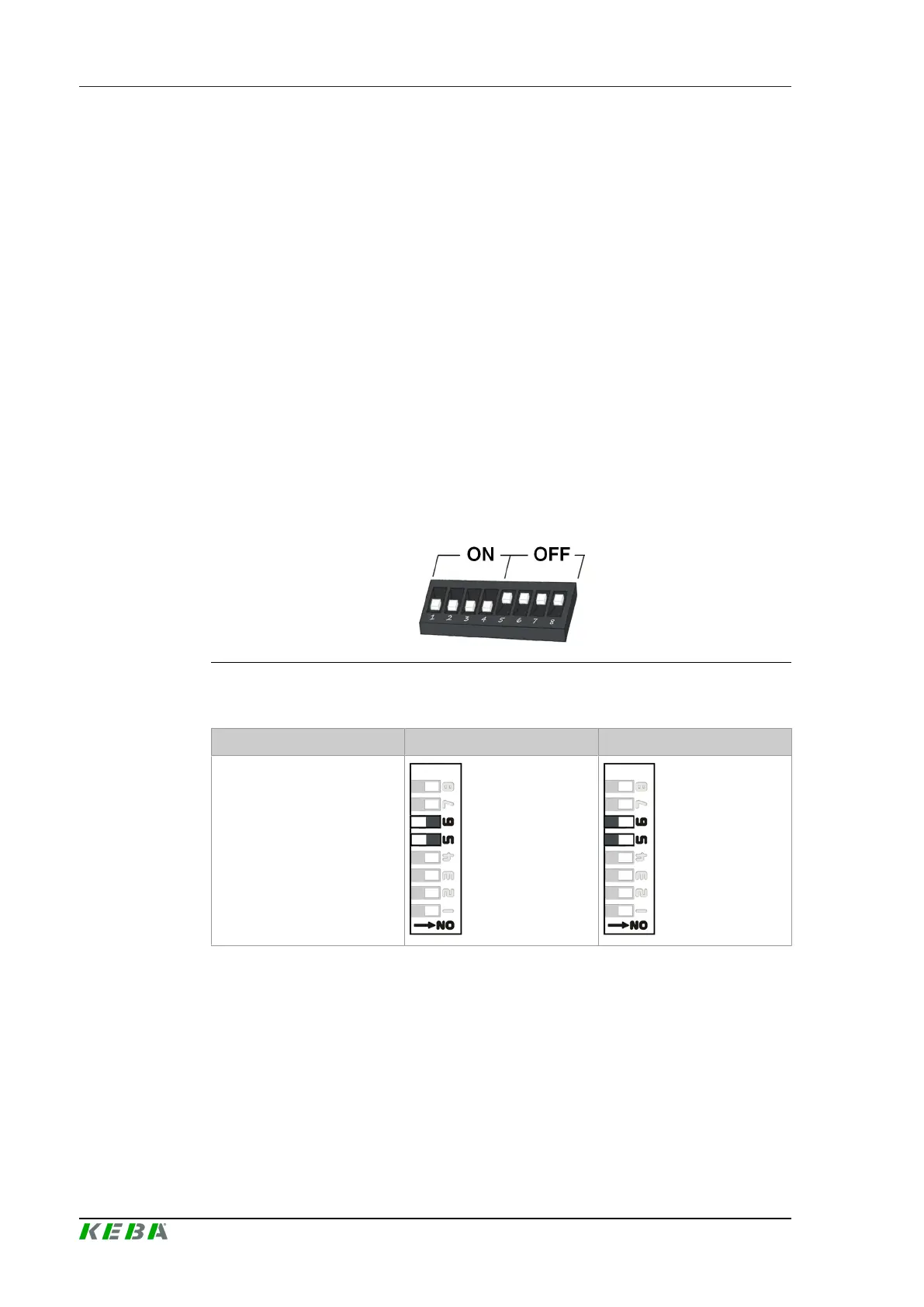
ON/OFF position of the switches
The illustration shows the position of the switches for the setting ON and
OFF.
Fig.7-42: Position of switches
DIP switch setting options
OFF ON
CAN
7.2 Serial interface configuration
The serial interfaces can be used for the connection of input/output devices.
They can be used ether as RS-232-C, RS-485-A or RS-422-A (changeable
via configuration tool).
In case of bus termination the termination for RS-485-A and RS-422-A must
be considered. RS-232-C does not need a bus termination. For further infor-
mation see "Bus termination" of the serial interfaces.
 Loading...