OUTPUT HI
(CENTER TRIAX CONDUCTOR)
I
250V
RMS MAX
I
f IOOV MAX
I
250V
RMS MAX
OUTPUT COMMON
(INNER TRIAX SHIELD)
CHASSIS COMMON
(OUTER TRIAX SHIELD)
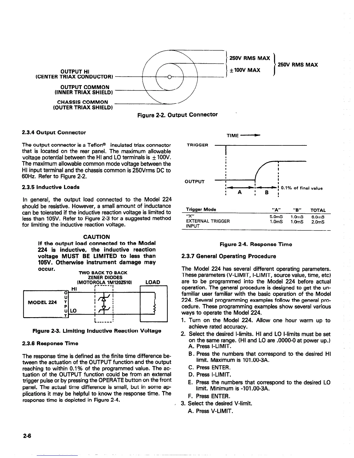
Figure 2-2. Output Connector
2.3.4 Output Connector
The output connector is a Teflon@
insulated triax connector
that is located on the rear panel. The maximum allowable
voltage potential between the HI and LO terminals is f 1OOV.
The maximum allowable common mode voltage between the
HI input terminal and the chassis common is 250Vrms DC to
60Hz. Refer to Figure 2-2.
2.3.5 Inductive Loads
In general, the output load connected to the Model 224
should be resistive. However, a small amount of inductance
can be tolerated if the inductive reaction voltage is limited to
less than 105V. Refer to Figure 2-3 for a suggested method
for limiting the inductive reaction voltage.
CAUTION
If the output load connected to the Model
224 is inductive, the inductive reaction
voltage MUST BE LIMITED to less than
105V. Otherwise instrument damage may
occur.
TWO BACK TO BACK
ZENER DIODES
~MOTOl?~CI~~~12OZ5lO~
LOAD
Figure 2-3. Limiting Inductive Reaction Voltage
2.3.6 Response Time
The response time is defined as the finite time difference be-
tween the actuation of the OUTPUT function and the output
reaching to within 0.1% of the programmed value. The ac-
tuation of the OUTPUT function could be from an external
trigger pulse or by pressing the OPERATE button on the front
panel. The actual time difference is small, but in some ap-
plications it may be helpful to know the response time. The
response time is depicted in Figure 2-4.
TIME -
TRIGGER
OUTPUT
p=
:-i-i 0.1% of final value
4
,
A :B!
Trigger Mode
“X’
EXTERNAL TRIGGER
INPUT
“A”
“B”
TOTAL
5.0mS
1 .OmS
6.0mS
l.OmS
1 .OmS
2.0mS
-
Figure 2-4. Response Time
2.3.7 General Operating Procedure
The Model 224 has several different operating parameters.
These parameters W-LIMIT, I-LIMIT, source value, time, etc)
are to be programmed into the Model 224 before actual
operation. The general procedure is designed to get the un-
familiar user familiar with the basic operation of the Model
224. Several programming examples follow the general pro-
cedure. These programming examples show several various
ways to operate the Model 224.
1. Turn on the Model 224. Allow one hour warm up to
achieve rated accuracy.
2. Select the desired l-limits. HI and LO l-limits must be set
on the same range. (HI and LO are .0000-O at power up.)
A. Press I-LIMIT.
B. Press the numbers that correspond to the desired HI
limit. Maximum is lOl.OO-3A.
C. Press ENTER.
D. Press I-LIMIT.
E. Press the numbers that correspond to the desired LO
limit. Minimum is -101 .OO-3A.
F. Press ENTER.
I 3. Select the desired V-limit.
A. Press V-LIMIT.
2-6

 Loading...


