5.1 INTRODUCTION
SECTION 5
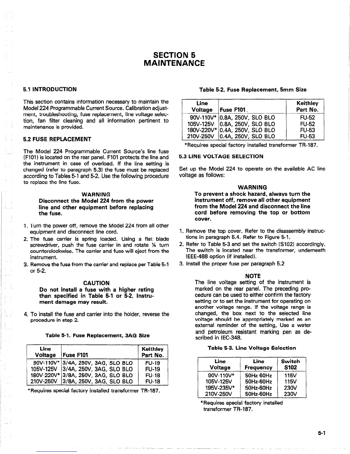
MAINTENANCE
Table 5-2. Fuse Replacement, 5mm Size
This section contains information necessary to maintain the
Model 224 Programmable Current Source. Calibration adjust-
ment, troubleshooting, fuse replacement, line voltage selec-
tion, fan filter cleaning and all information pertinent to
maintenance is provided.
5.2 FUSE REPLACEMENT
The Model 224 Programmable Current Source’s line fuse
(FlOl) is located on the rear panel. FIOI protects the line and
the instrument in case of overload. If the line setting is
changed (refer to paragraph 5.31 the fuse must be replaced
according to Tables 5-1 and 5-2. Use the following procedure
to replace the line fuse.
‘~~
*Requires special factory installed transformer TR-187.
5.3 LINE VOLTAGE SELECTION
Set up the Model 224 to operate on the available AC line
voltage as follows:
WARNING
Disconnect the Model 224 from the power
line and other equipment before replacing
the fuse.
1. Turn the power off, remove the Model 224 from all other
equipment and disconnect line cord.
2. The fuse carrier is spring loaded. Using a flat blade
screwdriver, push the fuse carrier in and rotate % turn
counterclockwise. The carrier and fuse will eject from the
instrument.
3. Remove the fuse from the carrier and replace per Table 5-1
or 5-2.
CAUTION
Do not install a fuse with a higher rating
than specified in Table 5-l or 5-2. Instru-
ment damage may result.
4. To install the fuse and carrier into the holder, reverse the
procedure in step 2.
Table 5-1. Fuse Replacement, 3AG Size
Line
Keithley
Voltage Fuse F101
Part No.
9OV-11OV” 3/4A, 25OV, 3AG, SLO BLO
FU-19
105V-125V 3/4A, 25OV, 3AG, SLO BLO
FU-19 I
18OV-22OV* 3/8A, 25OV, 3AG, SLO BLO
FU-18
21OV-250V 3/8A, 25OV, 3AG, SLO BLO
FU-18
*Requires special factory installed transformer TR-187.
WARNING
To prevent a shock hazard, always turn the
instrument off, remove all other equipment
from the Model 224 and disconnect the line
cord before removing the top or bottom
cover.
1. Remove the top cover. Refer to the disassembly instruc-
tions in paragraph 5.4. Refer to Figure 5-l.
2. Refer to Table 5-3 and set the switch (S102) accordingly.
The switch is located near the transformer, underneath
IEEE-488 option (if installed).
3. Install the proper fuse per paragraph 5.2
NOTE
The line voltage setting of the instrument is
marked on the rear panel. The preceding pro-
cedure can be used to either confirm the factory
setting or to set the instrument for operating on
another voltage range. If the voltage range is
changed, the box next to the selected line
voltage should be appropriately marked as an
external reminder of the setting, Use a water
and petroleum resistant marking pen as de-
scribed in IEC-348.
Table 5-3. Line Voltage Selection
*Requires special factory installed
transformer TR-187.
5-l

 Loading...


