- . . - m s- . .-a- ^_ . . ^
. . . - .
1
able
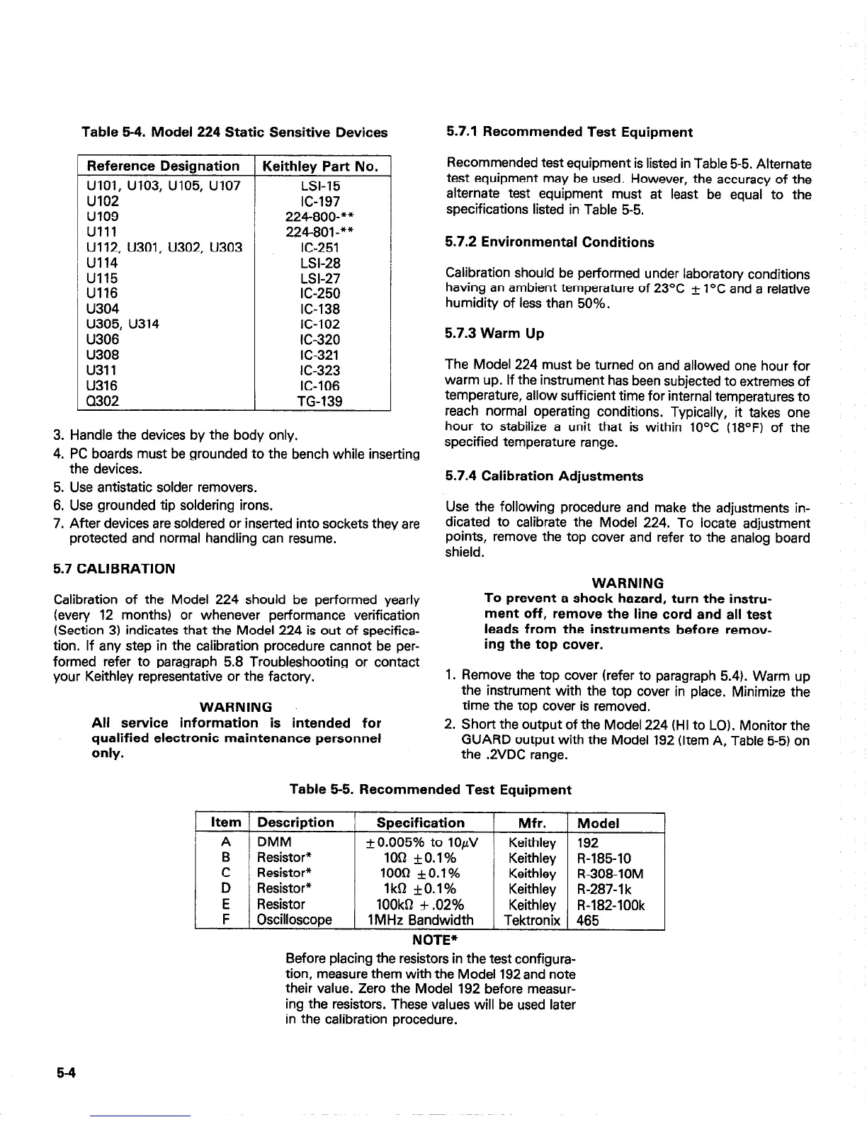
54. iwoael 224 static sensitive Devices
3. Handle the devices by the body only.
4. PC boards must be grounded to the bench while inserting
the devices.
Reference Designation Keithley Part No.
UlOl, u103, u105, u107
LSI-15
u102 IC-197
u109 224800-**
Ulll 224801-**
U112, U301, U302, U303 IC-251
u114
LSI-28
u115 LSI-27
U116 IC-250
u304 IC-138
u305, u314
IC-102
U306
IC-320
U308
IC-321
u311 IC-323
U316 IC-106
Q302 TG-139
J
5. Use antistatic solder removers.
6. Use grounded tip soldering irons.
7. After devices are soldered or inserted into sockets they are
protected and normal handling can resume.
5.7 CALIBRATION
Calibration of the Model 224 should be performed yearly
(every 12 months) or whenever performance verification
(Section 3) indicates that the Model 224 is out of specifica-
tion. If any step in the calibration procedure cannot be per-
formed refer to paragraph 5.8 Troubleshooting or contact
your Keithley representative or the factory.
WARNING
All service information is intended for
qualified electronic maintenance personnel
only.
5.7.1 Recommended Test Equipment
Recommended test equipment is listed in Table 5-5. Alternate
test equipment may be used. However, the accuracy of the
alternate test equipment must at least be equal to the
specifications listed in Table 5-5.
5.7.2 Environmental Conditions
Calibration should be performed under laboratory conditions
having an ambient temperature of 23OC + l°C and a relative
humidity of less than 50%.
5.7.3 Warm Up
The Model 224 must be turned on and allowed one hour for
warm up. If the instrument has been subjected to extremes of
temperature, allow sufficient time for internal temperatures to
reach normal operating conditions. Typically, it takes one
hour to stabilize a unit that is within 10°C (18OF) of the
specified temperature range.
5.7.4 Calibration Adjustments
Use the following procedure and make the adjustments in-
dicated to calibrate the Model 224. To locate adjustment
points, remove the top cover and refer to the analog board
shield.
WARNING
To prevent a shock hazard, turn the instru-
ment off, remove the line cord and all test
leads from the instruments before remov-
ing the top cover.
1. Remove the top cover (refer to paragraph 5.4). Warm up
the instrument with the top cover in place. Minimize the
time the top cover is removed.
2. Short the output of the Model 224 (HI to LOI. Monitor the
GUARD output with the Model 192 (Item A, Table 5-5) on
the .2VDC range.
Table 5-5. Recommended Test Equipment
Item Description
Specification
Mfr. Model
A
DMM
+0.005% to 10/N
Keithley 192
B Resistor*
1OQ *O.l%
Keithley R-185-10
C
Resistor*
1000 *O.l%
Keithley R-308-10M
D
Resistor*
1kB +O.l%
Keithley R-287-l k
E Resistor
100kQ f .02%
Keithley R-182-100k
F
Oscilloscope
1 MHz Bandwidth
Tektronix 465
NOTE*
Before placing the resistors in the test configura-
tion, measure them with the Model 192 and note
their value. Zero the Model 192 before measur-
ing the resistors. These values will be used later
in the calibration procedure.
5-4

 Loading...


