2.4.4 Low Resistance “Lindeck” Measurements
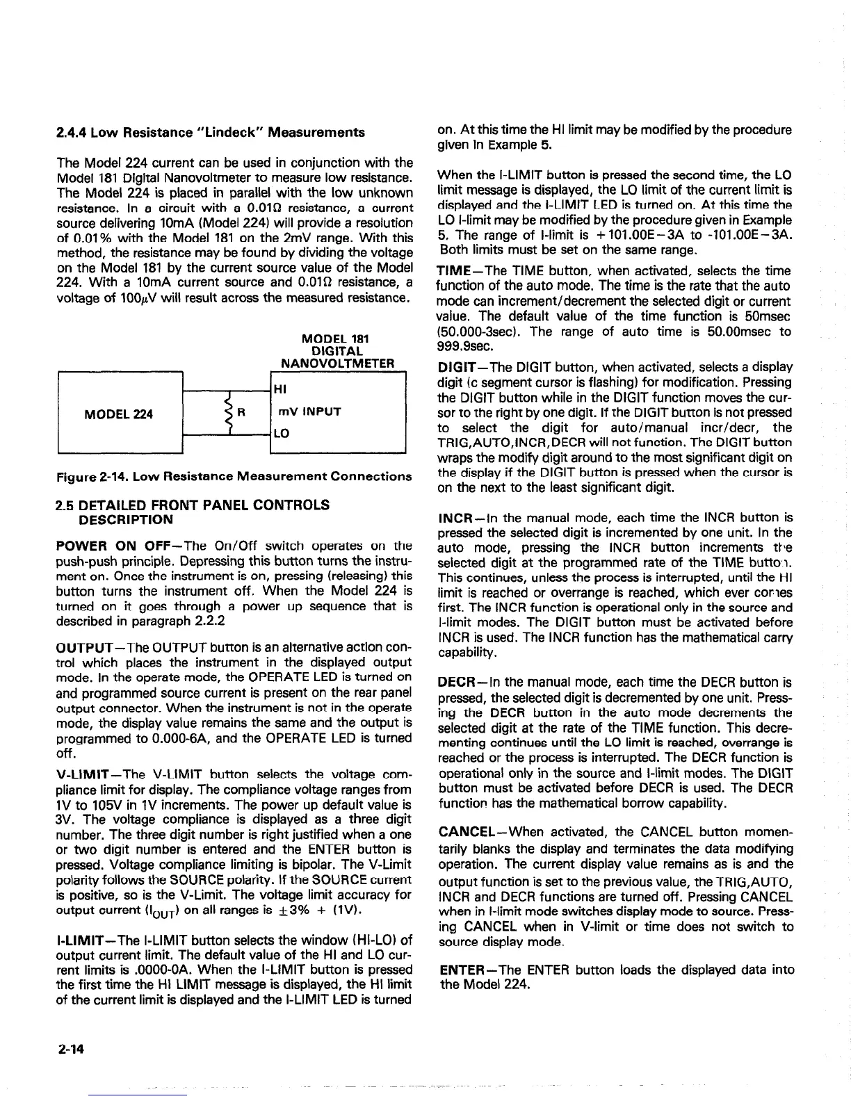
The Model 224 current can be used in conjunction with the
Model 181 Digital Nanovoltmeter to measure low resistance.
The Model 224 is placed in parallel with the low unknown
resistance. In a circuit with a O.OlD resistance, a current
source delivering IOmA (Model 224) will provide a resolution
of 0.01% with the Model 181 on the 2mV range. With this
method, the resistance may be found by dividing the voltage
on the Model 181 by the current source value of the Model
224. With a IOmA current source and O.OlQ resistance, a
voltage of IOOhV will result across the measured resistance.
MODEL 181
DIGITAL
NANOVOLTMETER
Figure 2-14. Low Resistance Measurement Connections
2.5 DETAILED FRONT PANEL CONTROLS
DESCRIPTION
POWER ON OFF-The On/Off switch operates on the
push-push principle. Depressing this button turns the instru-
ment on. Once the instrument is on, pressing (releasing) this
button turns the instrument off. When the Model 224 is
turned on it goes through a power up sequence that is
described in paragraph 2.2.2
OUTPUT-The OUTPUT button is an alternative action con-
trol which places the instrument in the displayed output
mode. In the operate mode, the OPERATE LED is turned on
and programmed source current is present on the rear panel
output connector. When the instrument is not in the operate
mode, the display value remains the same and the output is
programmed to O.OOO-6A, and the OPERATE LED is turned
Off.
V-LIMIT-The V-LIMIT button selects the voltage com-
pliance limit for display. The compliance voltage ranges from
IV to 105V in 1V increments. The power up default value is
3V. The voltage compliance is displayed as a three digit
number. The three digit number is right justified when a one
or two digit number is entered and the ENTER button is
pressed. Voltage compliance limiting is bipolar. The V-Limit
polarity follows the SOURCE polarity. If the SOURCE current
is positive, so is the V-Limit. The voltage limit accuracy for
output current (I,,,
1 on all ranges is +3% + (1V).
I-LIMIT-The I-LIMIT button selects the window (HI-LO) of
output current limit. The default value of the HI and LO cur-
rent limits is .OOOO-OA. When the I-LIMIT button is pressed
the first time the HI LIMIT message is displayed, the HI limit
of the current limit is displayed and the I-LIMIT LED is turned
2-14
on. At this time the HI limit may be modified by the procedure
given in Example 5.
When the I-LIMIT button is pressed the second time, the LO
limit message is displayed, the LO limit of the current limit is
displayed and the I-LIMIT LED is turned on. At this time the
LO l-limit may be modified by the procedure given in Example
5, The range of l-limit is + 101 .OOE -3A to -101 .OOE -3A.
Both limits must be set on the same range.
TIME-The TIME button, when activated, selects the time
function of the auto mode. The time is the rate that the auto
mode can increment/decrement the selected digit or current
value. The default value of the time function is 50msec
(50.000-3sec). The range of auto time is 50.00msec to
999.9sec.
DIGIT-The DIGIT button, when activated, selects a display
digit (c segment cursor is flashing) for modification. Pressing
the DIGIT button while in the DIGIT function moves the cur-
sor to the right by one digit. If the DIGIT button is not pressed
to select the digit for auto/manual incr/decr, the
TRIG,AUTO,INCR,DECR will not function. The DIGIT button
wraps the modify digit around to the most significant digit on
the display if the DIGIT button is pressed when the cursor is
on the next to the least significant digit.
INCR-In the manual mode, each time the INCR button is
pressed the selected digit is incremented by one unit. In the
auto mode, pressing the INCR button increments the
selected digit at the programmed rate of the TIME button.
This continues, unless the process is interrupted, until the HI
limit is reached or overrange is reached, which ever comes
first. The INCR function is operational only in the source and
I-limit modes. The DIGIT button must be activated before
INCR is used. The INCR function has the mathematical carry
capability.
DECR-In the manual mode, each time the DECR button is
pressed, the selected digit is decremented by one unit. Press-
ing the DECR button in the
auto mode decrements the
selected digit at the rate of the TIME function. This decre-
menting continues until the LO limit is reached, overrange is
reached or the process is interrupted. The DECR function is
operational only in the source and l-limit modes. The DIGIT
button must be activated before DECR is used. The DECR
function has the mathematical borrow capability.
CANCEL-When activated, the CANCEL button momen-
tarily blanks the display and terminates the data modifying
operation. The current display value remains as is and the
output function is set to the previous value, the TRIG,AUTO,
INCR and DECR functions are turned off. Pressing CANCEL
when in l-limit mode switches display mode to source. Press-
ing CANCEL when in V-limit or time does not switch to
source display mode.
ENTER-The ENTER button loads the displayed data into
the Model 224.

 Loading...


