3. Program the Model 224 for an output of +.OOOO-3A with a
1 OV compliance limit. Locate and adjust R343 for areading
on the Model 192 of .OOOOOO ?&V.
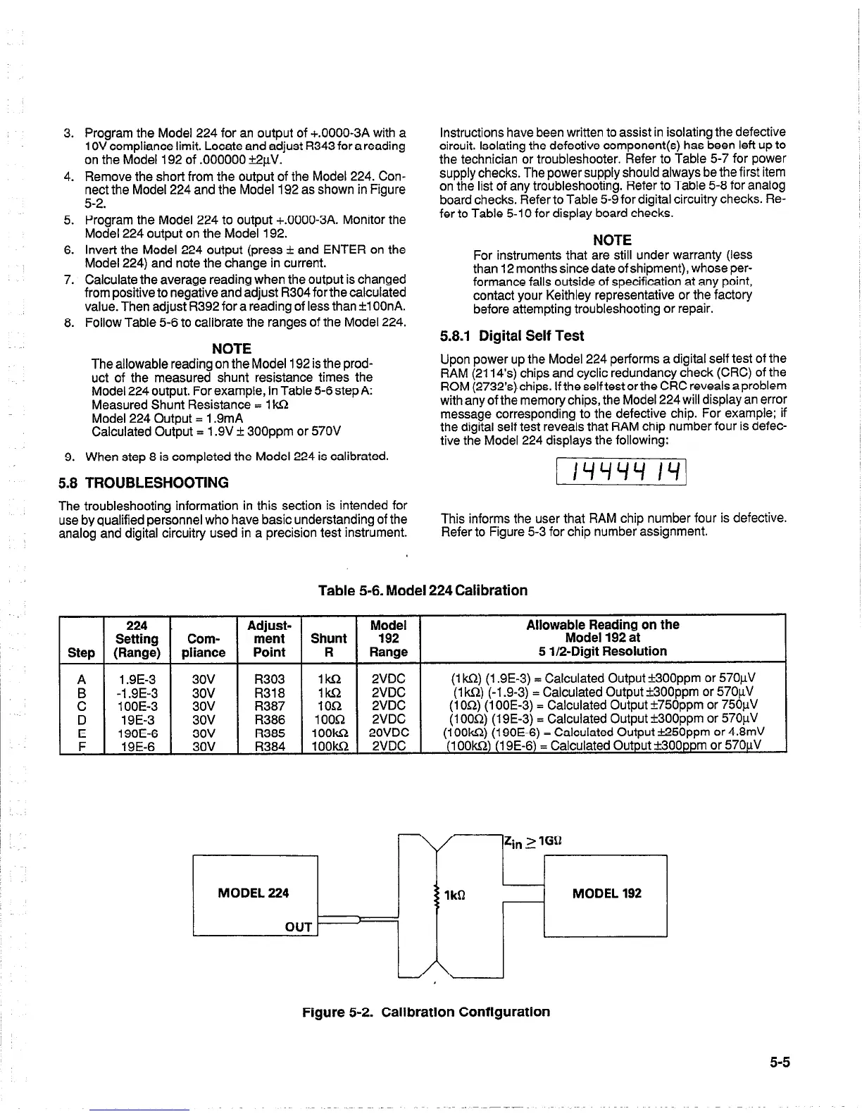
4. Remove the short from the output of the Model 224. Con-
nect the Model 224 and the Model 192 as shown in Figure
5-2.
5. Program the Model 224 to output +.OOOO-3A. Monitor the
Model 224 output on the Model 192.
6. Invert the Model 224 output (press + and ENTER on the
Model 224) and note the change in current.
7. Calculate the average reading when the output is changed
from positive to negative and adjust R304 forthe calculated
value. Then adjust R392 for a reading of less than +l OOnA.
8. Follow Table 5-6 to calibrate the ranges of the Model 224.
NOTE
The allowable reading on the Model 192 is the prod-
uct of the measured shunt resistance times the
Model 224 output. For example, in Table 5-6 step A:
Measured Shunt Resistance = 1 Wz
Model 224 Output = 1.9mA
Calculated Output = 1.9V + 300ppm or 570V
9. When step 8 is completed the Model 224 is calibrated.
5.8 TROUBLESHOOTING
The troubleshooting information in this section is intended for
use by qualified personnel who have basic understanding of the
analog and digital circuitry used in a precision test instrument.
Instructions have been written to assist in isolating the defective
circuit. Isolating the defective component(s) has been left up to
the technician or troubleshooter. Refer to Table 5-7 for power
supply checks. The power supply should always be the first item
on the list of any troubleshooting. Refer to Table 5-8 for analog
board checks. Refer to Table 5-9 for digital circuitry checks. Re-
fer to Table 5-l 0 for display board checks.
NOTE
For instruments that are still under warranty (less
than 12 months since date of shipment), whose per-
formance falls outside of specification at any point,
contact your Keithley representative or the factory
before attempting troubleshooting or repair.
5.8.1 Digital Self Test
Upon power up the Model 224 performs a digital self test of the
RAM (2114’s) chips and cyclic redundancy check (CRC) of the
ROM (2732’s).chips. If the selftest or the CRC reveals a problem
with any of the memory chips, the Model 224 will display an error
message corresponding to the defective chip. For example; if
the digital self test reveals that RAM chip number four is defec-
tive the Model 224 displays the following:
This informs the user that RAM chip number four is defective.
Refer to Figure 5-3 for chip number assignment.
Table 5-6. Model 224 Calibration
224
Adjust-
Setting
Com-
ment
Step (Range)
pliance Point
A 1.9E-3 3ov
R303
:
-1.9E-3 3ov
R318
1 OOE-3 3ov
R387
D
19E-3 3ov R386
E 190E-6
3ov
R385
F
19E-6
3ov R384
IkL-2
2VDC
1m 2VDC
-L
IOR 2VDC
1 ooln
2VDC
lOOki
20VDC
1ookR 2VDC
Allowable Reading on the
Model 192 at
5 l/a-Digit Resolution
(1 ks1) (1.9E-3) = Calculated Output +300ppm or 57OuV
(1 kR) (-1.9-3) = Calculated Output &3OOppm or 57OuV
(1 OR) (1 OOE-3) = Calculated Output ?750ppm or 75OuV
(1 OOQ) (19E-3) = Calculated Output +300ppm or 57OuV
(1 OOkn) (190E-6) = Calculated Output %??50ppm or 4.8mV
(1 OOk!Z) (19E-6) = Calculated Output f300ppm or 57OuV
Figure 5-2. Calibration Configuration
5-5

 Loading...


