CAUTION
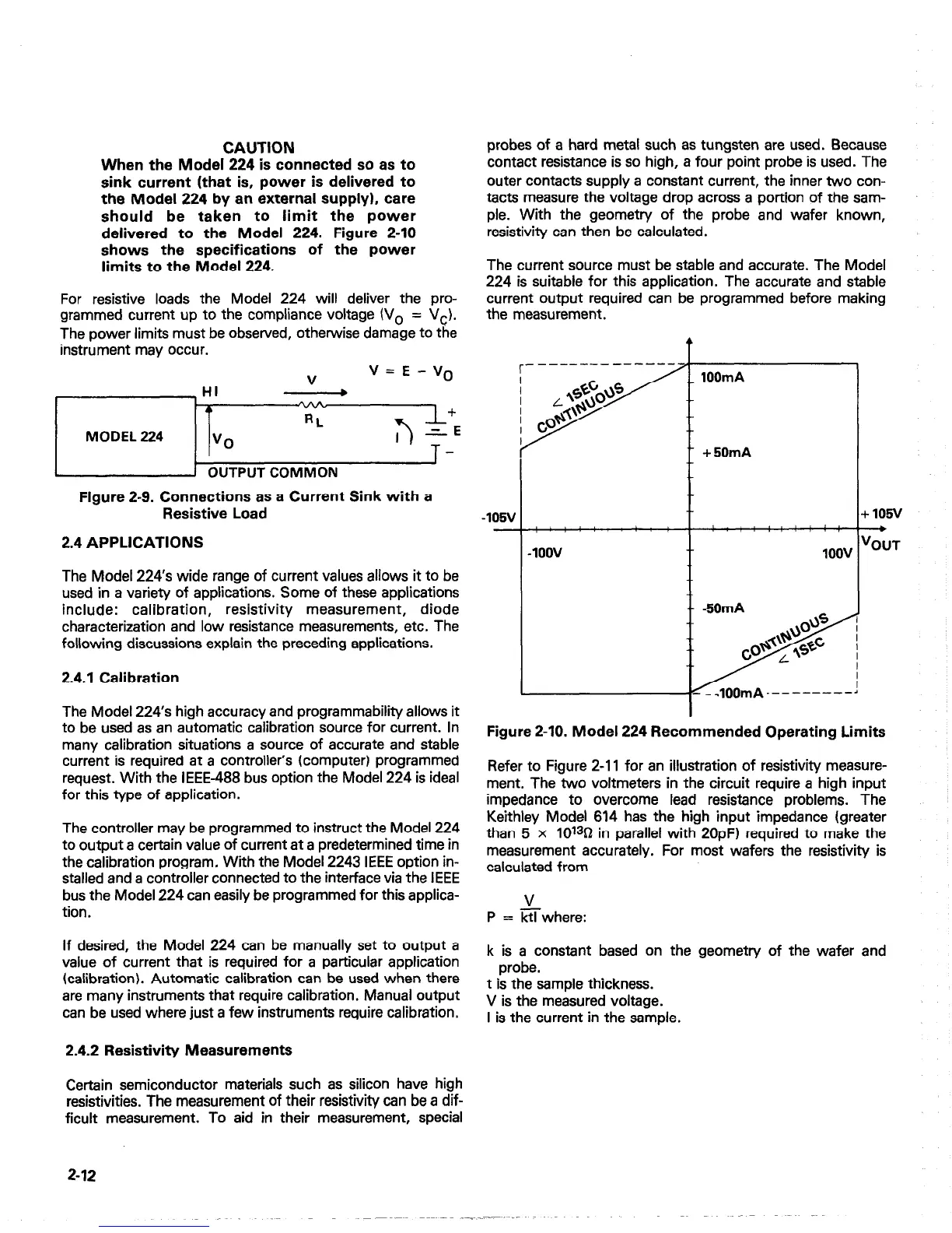
When the Model 224 is connected so as to
sink current (that is, power is delivered to
the Model 224 by an external supply). care
should be taken to limit the power
delivered to the Model 224. Figure 2-10
shows the specifications of the power
limits to the Model 224.
For resistive loads the Model 224 will deliver the pro-
grammed current up to the compliance voltage (V, = Vc).
The power limits must be observed, otherwise damage to the
instrument may occur.
r
MODEL 224
J
OUTPUT COMMON
Figure 2-9. Connections as a Current Sink with a
Resistive Load
2.4 APPLICATIONS
The Model 224’s wide range of current values allows it to be
used in a variety of applications. Some of these applications
include: calibration,
resistivity measurement, diode
characterization and low resistance measurements, etc. The
following discussions explain the preceding applications.
2.4.1 Calibration
The Model 224’s high accuracy and programmability allows it
to be used as an automatic calibration source for current. In
many calibration situations a source of accurate and stable
current is required at a controller’s (computer) programmed
request. With the IEEE-488 bus option the Model 224 is ideal
for this type of application.
The controller may be programmed to instruct the Model 224
to output a certain value of current at a predetermined time in
the calibration program, With the Model 2243 IEEE option in-
stalled and a controller connected to the interface via the IEEE
bus the Model 224 can easily be programmed for this applica-
tion.
If desired, the Model 224 can be manually set to output a
value of current that is required for a particular application
(calibration). Automatic calibration can be used when there
are many instruments that require calibration. Manual output
can be used where just a few instruments require calibration.
2.4.2 Resistivity Measurements
Certain semiconductor materials such as silicon have high
resistivities. The measurement of their resistivity can be a dif-
ficult measurement. To aid in their measurement, special
2-12
probes of a hard metal such as tungsten are used. Because
contact resistance is so high, a four point probe is used. The
outer contacts supply a constant current, the inner two con-
tacts measure the voltage drop across a portion of the sam-
ple. With the geometry of the probe and wafer known,
resistivity can then be calculated.
The current source must be stable and accurate. The Model
224 is suitable for this application. The accurate and stable
current output required can be programmed before making
the measurement.
r-
4
,100v
IOOV
T
.- -5OmA
,
b 105v
--+
{OUT
Figure 2-10. Model 224 Recommended Operating Limits
Refer to Figure 2-11 for an illustration of resistivity measure-
ment. The two voltmeters in the circuit require a high input
impedance to overcome lead resistance problems. The
Keithley Model 614 has the high input impedance (greater
than 5 x 10130 in parallel with 2OpF) required to make the
measurement accurately. For most wafers the resistivity is
calculated from
V
P = ktlwhere:
k is a constant based on the geometry of the wafer and
probe.
t is the sample thickness.
V is the measured voltage.
I is the current in the sample.

 Loading...


