EasyManua.ls Logo

Keithley 2601 User Manual

Keithley 2601
114 pages
To Next Page IconTo Next Page
To Previous Page IconTo Previous Page
Page #22 background image
1-8 Return to Section Topics 2600S-900-01 Rev. C / January 2008
Section 1: Front and Rear Panel Operation Series 2600 System SourceMeter
®
Instruments User’s Manual
Figure 1-3
Model 2635 and 2636 rear panel
CHANNEL B
SENSE
LO
LO
GUARD
SENSE
HI
HI
CHANNEL B
SENSE
LO
LO
GUARD
SENSE
HI
HI
WARNING:NO INTERNAL OPERATOR SERVICABLE PARTS,SERVICE BY QUALIFIED PERSONNEL ONLY.
CAUTION:FOR CONTINUED PROTECTION AGAINST FIRE HAZARD,REPLACE FUSE WITH SAME TYPE AND RATING.
WARNING:NO INTERNAL OPERATOR SERVICABLE PARTS,SERVICE BY QUALIFIED PERSONNEL ONLY.
CAUTION:FOR CONTINUED PROTECTION AGAINST FIRE HAZARD,REPLACE FUSE WITH SAME TYPE AND RATING.
MADE IN
U.S.A.
IEEE-488
LINE RATING
100-240VAC
50, 60Hz
240VA MAX.
DIGITAL I/O
RS-232
TSP-Link
LINE FUSE
SLOWBLOW
3.15A, 250V
MADE IN
U.S.A.
IEEE-488
LINE RATING
100-240VAC
50, 60Hz
240VA MAX.
DIGITAL I/O
RS-232
TSP-Link
LINE FUSE
SLOWBLOW
3.15A, 250V
!
!
A LO
A LOB LO
R
CHANNEL A
SENSE
LO
LO
GUARD
SENSE
HIHI
CHANNEL B
SENSE
LO
LO
GUARD
SENSE
HI
HI
R
Model 2635
Model 2636
1
2
3
4
56 7
8
1
2
3
67
8
1
5
910
4
910
CHANNEL A
SENSE
LO
LO
GUARD
SENSE
HIHI
s

Table of Contents

Other manuals for Keithley 2601

Question and Answer IconNeed help?

Do you have a question about the Keithley 2601 and is the answer not in the manual?

Keithley 2601 Specifications

General IconGeneral
Model2601
TypeSourceMeter
Channels1
Voltage Range±40V
Maximum Voltage40 V
Current Range±3A
Maximum Current3 A
Power20 W
Current Resolution10 pA
Measurement Resolution6.5 digits
Voltage Resolution100nV
ConnectivityUSB, GPIB, Ethernet
Communication InterfaceGPIB, RS-232

Summary

Front and Rear Panel Operation

Instrument Layout and Familiarization

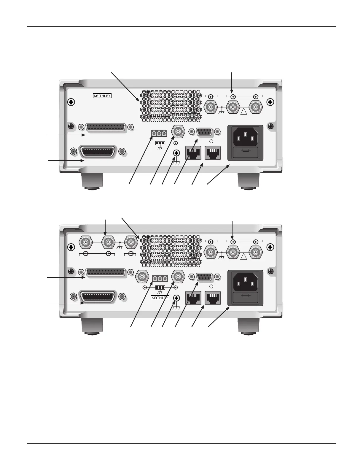
Overview of front and rear panel controls and layout.

Safety Symbols and Terms

Explanation of safety icons and terminology used in the manual.

Source-Measure Capabilities Overview

Details the voltage and current sourcing and measuring specifications.

Instrument Power-Up Procedure

Step-by-step guide for connecting and powering on the instrument.

Performing Basic Measurements

Procedure for setting up and executing voltage/current measurements.

Using Instrument Data Buffers

Instructions for storing and recalling measurement data using internal buffers.

Remote Operation

Remote Interface Configuration

Setup for GPIB and RS-232 communication interfaces.

Test Script Builder (TSB) Introduction

Overview of the TSB software and its interface elements.

Making Measurements with TSB

Step-by-step guide for using TSB to control the instrument and take measurements.

Integrating with External Software

Examples of controlling the instrument using LabVIEW and Visual Basic.

Test Script Processor Interaction

Understanding Test Scripts

Definition and types of scripts (factory vs. user).

Running Scripts from the Front Panel

Procedure for executing scripts directly from the instrument.

Interacting with Scripts via Test Script Builder

Demonstrates running and modifying scripts using TSB.

Managing User Scripts

Procedures for adding, deleting, and executing custom user scripts.

Controlling Multiple Series 2600s (TSP-Link)

TSP-Link System Setup and Connections

Connecting instruments and forming a TSP-Link system.

Assigning Node Numbers

How to assign unique identifiers to instruments in a TSP-Link network.

TSP-Link Initialization and State Checking

Resetting the TSP-Link interface and verifying system communication status.

Expanded System Resource Access

Accessing instruments and running scripts across the TSP-Link system.

Specifications

Models 2601/2602 Specifications

Detailed technical and performance specifications for Models 2601 and 2602.

Models 2611/2612 Specifications

Detailed technical and performance specifications for Models 2611 and 2612.

Models 2635/2636 Specifications

Detailed technical and performance specifications for Models 2635 and 2636.

Series 2600 General Specifications

Overall specifications common to the Series 2600 product line.

Frequently Asked Questions

Optimizing Measurement Performance

Tips for adjusting settings to enhance speed and accuracy.

Digital I/O Port Configuration

How to utilize the Digital I/O port for control and triggering.

Instrument Triggering and Synchronization

Using Digital I/O to trigger other instruments or scanners.

Service Request (SRQ) Generation

Setting up and polling for instrument-generated service requests.

Non-Volatile Data Storage

Procedures for saving measurement data to internal memory.

Voltage Output Stacking

Connecting channels in series to achieve higher output voltages.

Current Output Paralleling

Connecting channels in parallel to achieve higher output currents.

Contact Check Measurement Procedures

Performing checks to detect poor connections or high resistance.

Low-Current Measurement Techniques

Methods and programming for accurate low-current measurements.

Related product manuals