EasyManua.ls Logo

Keithley 2601 User Manual

Keithley 2601
114 pages
To Next Page IconTo Next Page
To Previous Page IconTo Previous Page
Page #49 background imageLoading...
Page #49 background image
2600S-900-01 Rev. C / January 2008 Return to Section Topics 3-3
Series 2600 System SourceMeter
®
Instruments User’s Manual Section 3: Test Script Processor Interaction
Reading the buffer – Test data is stored in a buffer. See “How do I use the buffer?” on page 1-16
for details on recalling test data.
How do I interact with scripts using Test Script Builder?
Reference See “Using the Test Script Builder” in Section 2 of the Series 2600 Reference
Manual for details on the Test Script Builder.
The following function for factory script “KIGeneral” is stored in the non-volatile memory of the
Series 2600:
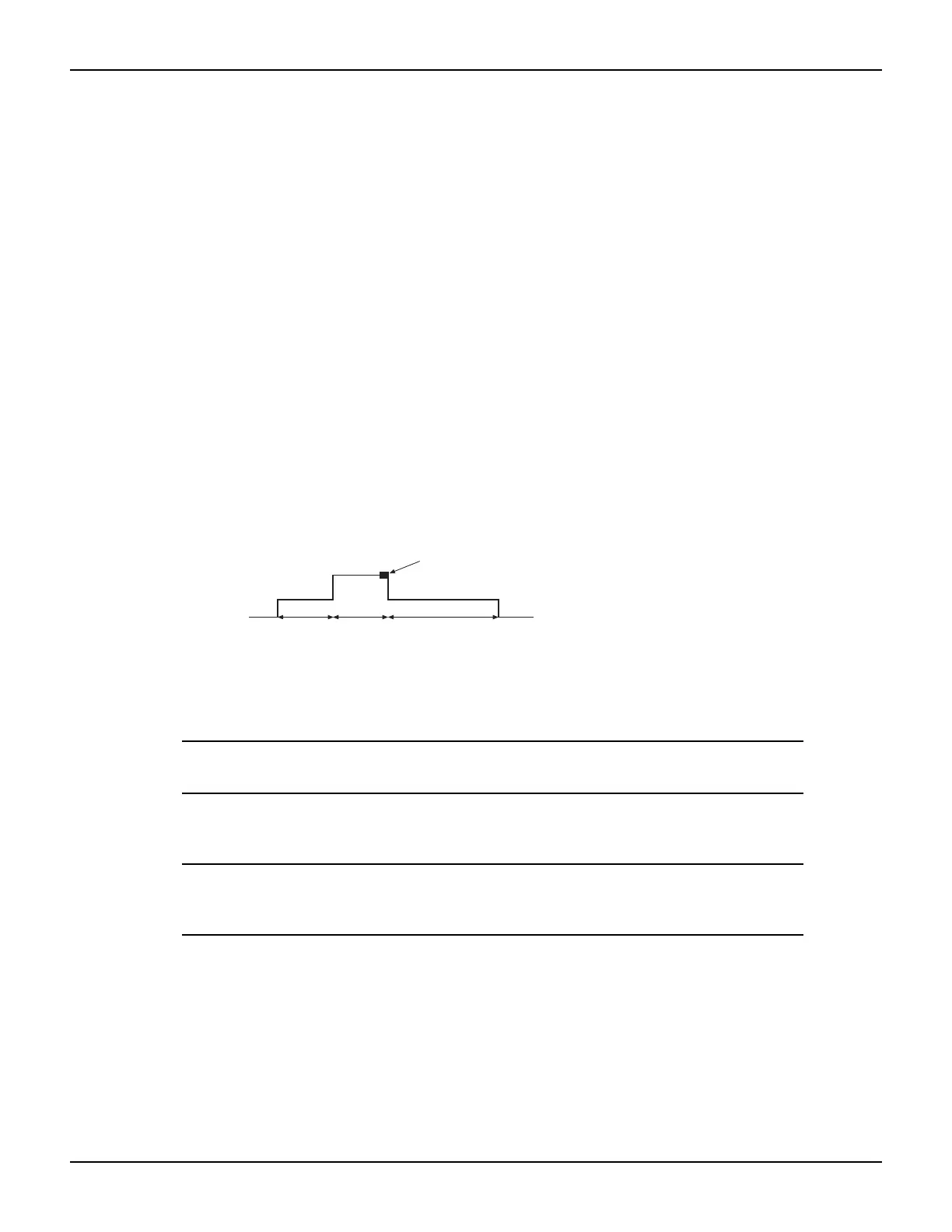
PulseVMeasureI(smu, bias, level, ton, toff, points)
The above function performs a specified number of pulse V, measure I cycles:
Sets the smu to output bias volts and dwell for ton seconds.
Sets the smu to output level volts and dwell for ton seconds.
Performs current measurement with the source at level volts.
Sets the smu to output bias volts for toff seconds.
Repeats the above sequence for points pulse-measure cycles.
Figure 3-1 shows one pulse-measure cycle for the function.
Figure 3-1
Pulse-measure cycle for the
level
bias
ton
bias
ton toff
Current measurement
PulseVMeasureI function
Running a factory script
Reference See “Factory scripts” in Section 2 of the Series 2600 Reference Manual for details
on running factory scripts.
NOTE All commands to run a factory script are to be executed from the
Instrument Console of the Test Script Builder.
The following steps explain how to run the PulseVMeasureI function and read the data stored in
the buffer.
NOTE The “KIGeneral” factory script is an autorun script. The script runs
automatically when the Series 2600 is turned on. The functions of the
script are ready to be called.
Step 1: Call the function
The following are example parameters for the PulseVMeasureI function which will perform three
pulse voltage, measure current cycles:
smu SMU A
bias -1V
level 1V
ton 1ms
toff 2ms

Table of Contents

Other manuals for Keithley 2601

Question and Answer IconNeed help?

Do you have a question about the Keithley 2601 and is the answer not in the manual?

Keithley 2601 Specifications

General IconGeneral
Model2601
TypeSourceMeter
Channels1
Voltage Range±40V
Maximum Voltage40 V
Current Range±3A
Maximum Current3 A
Power20 W
Current Resolution10 pA
Measurement Resolution6.5 digits
Voltage Resolution100nV
ConnectivityUSB, GPIB, Ethernet
Communication InterfaceGPIB, RS-232

Summary

Front and Rear Panel Operation

Instrument Layout and Familiarization

Overview of front and rear panel controls and layout.

Safety Symbols and Terms

Explanation of safety icons and terminology used in the manual.

Source-Measure Capabilities Overview

Details the voltage and current sourcing and measuring specifications.

Instrument Power-Up Procedure

Step-by-step guide for connecting and powering on the instrument.

Performing Basic Measurements

Procedure for setting up and executing voltage/current measurements.

Using Instrument Data Buffers

Instructions for storing and recalling measurement data using internal buffers.

Remote Operation

Remote Interface Configuration

Setup for GPIB and RS-232 communication interfaces.

Test Script Builder (TSB) Introduction

Overview of the TSB software and its interface elements.

Making Measurements with TSB

Step-by-step guide for using TSB to control the instrument and take measurements.

Integrating with External Software

Examples of controlling the instrument using LabVIEW and Visual Basic.

Test Script Processor Interaction

Understanding Test Scripts

Definition and types of scripts (factory vs. user).

Running Scripts from the Front Panel

Procedure for executing scripts directly from the instrument.

Interacting with Scripts via Test Script Builder

Demonstrates running and modifying scripts using TSB.

Managing User Scripts

Procedures for adding, deleting, and executing custom user scripts.

Controlling Multiple Series 2600s (TSP-Link)

TSP-Link System Setup and Connections

Connecting instruments and forming a TSP-Link system.

Assigning Node Numbers

How to assign unique identifiers to instruments in a TSP-Link network.

TSP-Link Initialization and State Checking

Resetting the TSP-Link interface and verifying system communication status.

Expanded System Resource Access

Accessing instruments and running scripts across the TSP-Link system.

Specifications

Models 2601/2602 Specifications

Detailed technical and performance specifications for Models 2601 and 2602.

Models 2611/2612 Specifications

Detailed technical and performance specifications for Models 2611 and 2612.

Models 2635/2636 Specifications

Detailed technical and performance specifications for Models 2635 and 2636.

Series 2600 General Specifications

Overall specifications common to the Series 2600 product line.

Frequently Asked Questions

Optimizing Measurement Performance

Tips for adjusting settings to enhance speed and accuracy.

Digital I/O Port Configuration

How to utilize the Digital I/O port for control and triggering.

Instrument Triggering and Synchronization

Using Digital I/O to trigger other instruments or scanners.

Service Request (SRQ) Generation

Setting up and polling for instrument-generated service requests.

Non-Volatile Data Storage

Procedures for saving measurement data to internal memory.

Voltage Output Stacking

Connecting channels in series to achieve higher output voltages.

Current Output Paralleling

Connecting channels in parallel to achieve higher output currents.

Contact Check Measurement Procedures

Performing checks to detect poor connections or high resistance.

Low-Current Measurement Techniques

Methods and programming for accurate low-current measurements.

Related product manuals