1-14 Performance Verification Model 2701 Service Manual
Verifying resistance
Check resistance by connecting accurate resistance values to the Model 2701 and verifying
that its resistance readings are within the specified limits.
CAUTION Do not apply more than 1000V peak between front terminals INPUT HI
and LO or more than 350V peak between SENSE HI and LO, or instru-
ment damage could occur.
Follow these steps to verify resistance accuracy:
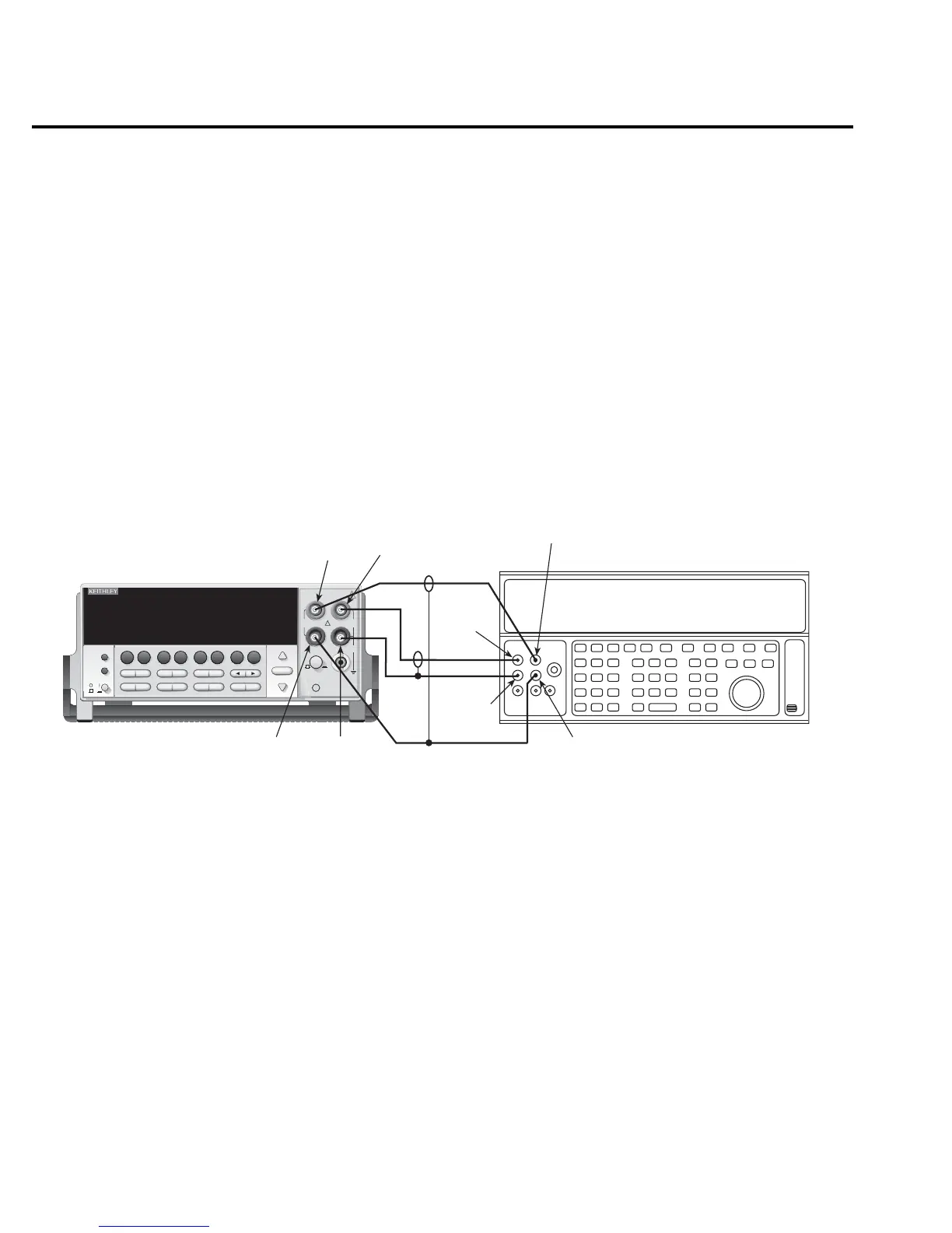
1. Using shielded, Teflon-insulated or equivalent cables in a 4-wire configuration, connect
the Model 2701 INPUT and SENSE jacks to the calibrator as shown in Figure 1-5. Be
sure the INPUTS switch is in the FRONT position.
Figure 1-5
Connections for Model 2701 resistance verification (100Ω to 10MΩ ranges)
2. Set the calibrator for 4-wire resistance with external sense on.
3. Select the Model 2701 4-wire resistance function by pressing the Ω4 key, then choose
the SLOW integration rate with the RATE key.
4. Set the Model 2701 for the 100Ω range and make sure the FILTER is on. Enable
OCOMP (offset-compensated ohms) for 100Ω range verification. (Press SHIFT then
OCOMP.)
5. Recalculate reading limits based on actual calibrator resistance values.
!
Model 2701 Ethernet Multimeter / Data Acquisition System
RANGE
F
500V
PEAK
FRONT/REAR
3A 250V
AMPS
HI
INPUT
LO
SENSE
Ω 4 WIRE
INPUTS
350V
PEAK
1000V
PEAK
AUTO
SHIFT
LOCAL
POWER
RANGE
R
EXIT ENTER
DIGITS RATE
RELFILTER
TRIG
EX TRIG
STORE
RECALL
OPEN
DCV
DCI
MATH
OUTPUT
RATIO
ACV
ACI
Ω2 Ω4
FREQ
TEMP
CH AVG
CONT
PERIOD SENSOR
LIMITS ON/OFFDELAY
HOLD
SAVE SETUP
CONFIG HALT
TYPE
LSYNC
TEST
MONITOR
STEP SCAN
OCOMP
CH-OFF CARD
CLOSE
Integra Series
RS-232ETHERNET
Resistance Calibrator
Note: Use shielded, low-thermal cables to
minimize noise. Enable or disable
calibrator external sense as indicated
in procedure.
Model 2701
SENSE HI
SENSE LO
OUTPUT
HI
OUTPUT
LO
INPUT
HI
SENSE
HI
SENSE
LO
INPUT
HI
CAT I

 Loading...


