Model 2701 Service Manual Troubleshooting 4-17
Table 4-13 through Table 4-17 can be used to trace the analog signal through the A/D multi-
plexer (U163) to the final amplifier stage. These tables show the MUX lines (S3, S4, S6, S7)
that are selected for measurement during the SIGNAL phase of the multiplexing cycle. Also
included are switching states of analog switches (U129) that set up the gain for the final ampli-
fier stage (U166).
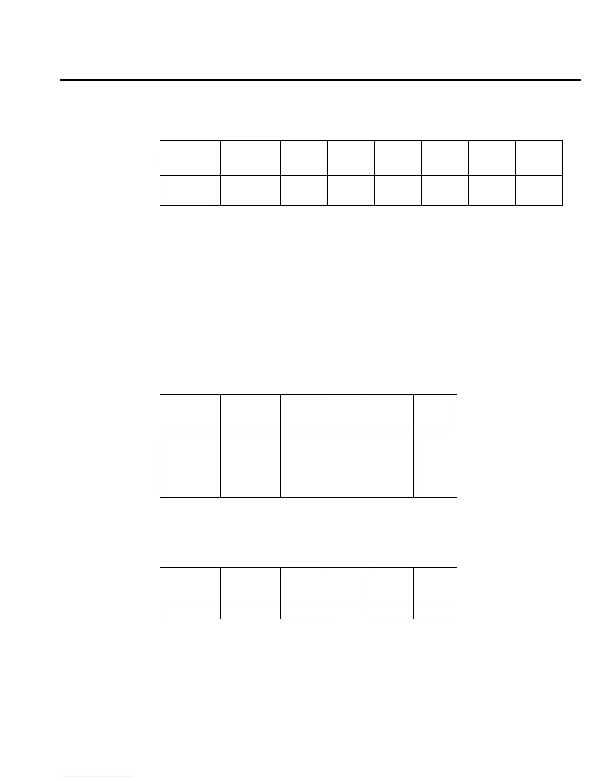
Table 4-12
ACA signal switching
Range K103*
U105
pin 16
U105
pin 1
U111
pin 16
U105
pin 8
U103
pin 16
U103
pin 1
1A
3A
Reset
Reset
ON
ON
ON
ON
OFF
ON
OFF
OFF
OFF
OFF
OFF
OFF
* K103 set states: Pin 8 to 7
Pin 3 to 4
K103 reset states: Pin 8 to 9
Pin 3 to 2
Table 4-13
DCV signal multiplexing and gain
Range
Signal
(U163)
U129
pin 1
U129
pin 8
U129
pin 9
Gain
(U166)
100mV
1V
10V
100V
1000V
S4
S4
S4
S4
S4
OFF
OFF
ON
OFF
ON
OFF
ON
OFF
ON
OFF
ON
OFF
OFF
OFF
OFF
×100
×10
×1
×10
×1
Table 4-14
ACV and ACA signal multiplexing and gain
Range
Signal
(U163)
U129
pin 1
U129
pin 8
U129
pin 9
Gain
(U166)
All S3 ON OFF OFF ×1

 Loading...


