Model 2790 SourceMeter
®
Switch System User’s Manual 2-21
Memory pattern commands
Memory patterns commands are summarized in Table 2-5. See Section 2 of the Model
2790 Reference Manual for details on these commands.
Setting up and executing memory patterns
To set up memory patterns, use the following procedure:
1. Program the desired memory pattern locations using the ROUT:MEM commands.
Typically, you would set source value(s), define channels to close, and set up delay
for each memory location.
2. Define DCV, 2-wire ohms, or 4-wire ohms measurement function(s) for each memory
pattern location.
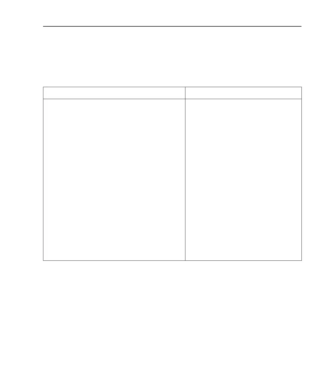
Command Description
:ROUTe:MEMory[:CHANnels] <n>, <clist> Create channel pattern for memory <n> (1-40).
Note: 7702 channels cannot be included in
<clist>.
:ROUTe:MEMory:SOURce:LEVel <n>, <NRf>, <clist> Assign source values to the channels in <clist>
that will be output when memory pattern <n>
is executed. (Source channels only: 127, 128,
227, or 228.)
:ROUTe:MEMory:DELay <n>, <NRf> Assign a variable delay to memory pattern
<n>. (Time in seconds after closing channels
and setting source values before making
measurements.)
:ROUTe:MEMory:RECall <n> Immediately execute memory pattern <n>.
:ROUTe:MEMory:READ[:STATe] <n>, <b> If set to ON, a reading will be collected after
the memory pattern has executed (applies to
scanning only). *
:ROUTe:MEMory:CLEar <n> Clear out memory pattern <n>, setting all
channels to open and removing all digital and
analog channels from this memory pattern.
:ROUTe:MEMory:CLEar:ALL Clear out all memory patterns.
* You must include at least one measurement channel or a memory pattern that takes a reading (ROUT:MEM:READ:STAT x, ON).
Failure to do so results in the scan list being rejected with Error +702, “No measurement channel in scanlist.”