Model 2790 SourceMeter
®
Switch System User’s Manual 5-11
When using the dry circuit, test current is automatically limited to slightly more than
1mA, regardless of the programmed level. Therefore, it is recommended that the I-source
output be set to 1mA or less to ensure that a known current is being used for the resistance
measurement.
NOTE The SxIohms math functions use the programmed I-source values for their cal-
culations. If the I-source output is not set to 1mA or less while dry circuit is
enabled (channel 24 closed), these math functions will give incorrect resistance
readings.
NOTE Typically, the shunt bar test is usually the first step in the testing process for an
inflator. The typical test station uses a spring-loaded mechanism that automati-
cally installs or removes the shunt bar.
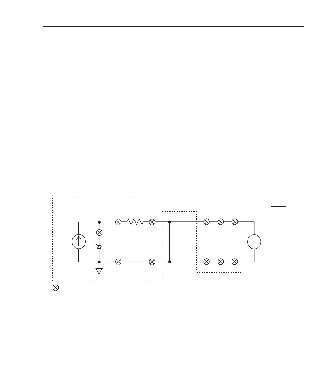
Test circuit
The circuit for the shunt bar test is shown in Figure 5-7. Note that the 20mV dry circuit
clamp is used for this test.
Figure 5-7
Test circuit – shunt bar
2790 DMM
v
Input HI
Input LO
17
17
18
18
I
SOURCE
*
21
21
20mV
Dry
Ckt
1Ω
24
Shunt Bar
Under
Test
= Closed channel switch
Test assumption: Shunt bar connected to Bank 1
RSHUNT =
V
MEAS
ISOUR
* Ch 22 open = I-source selected
NOTE Each channel (except channel 24) is a 2-pole
switch. Therefore, when a 2-pole channel is
closed, two switches close. Channel 24 is a
1-pole switch (see schematic in Figure 2-1).
Keithley 7751, 7752, or 7753
1 or 4*
2 or 5*
1 or 4*
2 or 5*
* Channels 4 and 5 used for dual inflator
where each bridgewire has its own shunt bar.
See Figure 5-8.
 Loading...
