5-30 Model 2790 SourceMeter
®
Switch System User’s Manual
Memory patterns test
As discussed in Section 2, Model 2790 units equipped with firmware revision A04 and
higher have the capability of using memory patterns to simplify repetitive test procedures.
The discussion below shows how to use memory patterns to make contact checks on a
dual-stage inflator.
NOTE See Section 2 of the Model 2790 Reference Manual for a more detailed memory
patterns example.
Test circuit
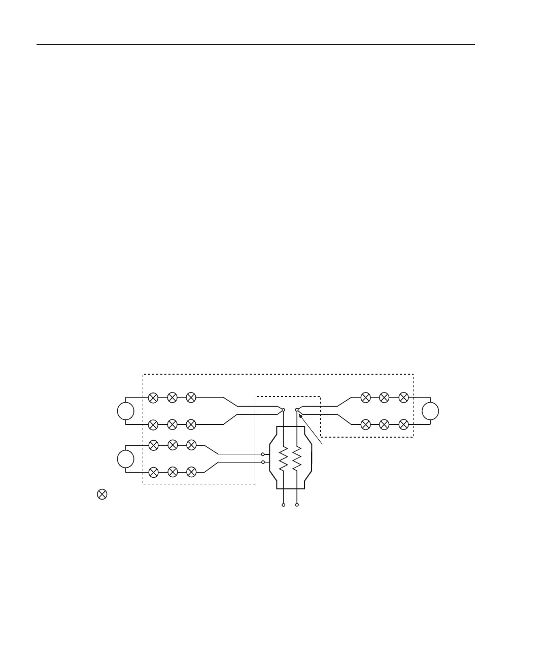
As shown in Figure 5-14, there are four contact connection points for the V-source test cir-
cuits. Contact checks are performed as follows:
• Bank 1 HI contact — Close channels 1, 14, and 18 to check the connection at the
HI terminal of bridgewire A.
• Bank 2 housing contact — Close channels 8, 15, and 18 to check the connection at
the housing of the inflator.
• Bank 3 HI contact — Close channels 4, 14, and 18 to check the connection at the
HI terminal of bridgewire B.
Figure 5-14
Test circuits – memory patterns – dual stage inflator contact test
1
Dual Stage
Inflator
2790
DMM
Lo
Lo
Ω2
2790
DMM
Hi
Ω2
Hi
2790
DMM
Hi
Hi
Ω2
A
B
14
8
15
4
14
Test assumptions:
Inflator housing connected to Bank 3
Bridgewire A connected to Bank 1
Bridgewire B connected to Bank 2
Bank 2
Bank 1
Bank 3
= Closed channel switch
Contact Point
(1 of 3)
18
18
18
NOTE Each channel is a 2-pole
switch. Therefore, when a
channel is closed, two
switches close (see
schematic in Figure 2-1).
Keithley 7751/7753
 Loading...
