Model 2790 SourceMeter
®
Switch System User’s Manual 5-9
Interlock connections:
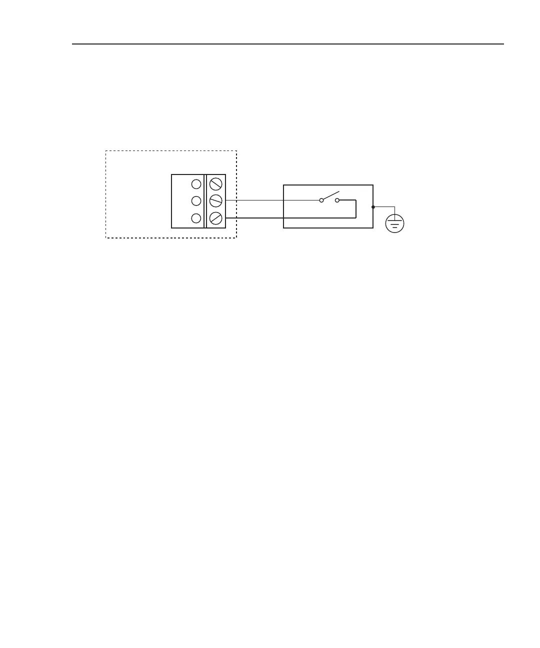
Figure 5-6 — When using a test fixture or safety shield that has an interlock switch, con-
nect interlock as shown in Figure 5-6.
Figure 5-6
Interlock connections
Interlock
NOTE An enabled interlock allows the I-source and V-source (7751/7753) to be con-
nected to the rest of the switch matrix. An open (disabled) interlock does not dis-
able the sources. The sources are always on and available at the J107 terminals
of the module. Interlock has no effect on the source outputs at J107.
The selected source can also be accessed at J105 (Source Hi and Source Lo)
when interlock is enabled. With interlock open, the sources are disconnected.
The interlock of the 7751/7752/7753 module must be enabled in order to connect the
I-source or V-source (7751/7753) to the rest of the switch matrix. With interlock disabled,
you will not be able to close switches that connect the selected source to the DUT and DMM.
The typical test station has a built-in interlock switch, which is to be connected to
INTERLOCK of the 7751/7752/7753. When the test station lid or safety shield is open,
the switch will open to disconnect the sources of the 7751/7752/7753.
Figure 5-6 shows how to connect the interlock of the 7751, 7752, or 7753 to the test station.
+5V
INTERLOCK
J106
Lid/shield open = switch open = Sources disconnected
Lid/shield closed = switch closed = Sources connected
Connect to safety earth
ground using #18 AWG
wire or larger.
Test Station
INTERLOCK
DO NOT permanently short out the interlock.
Interlock is an essential safeguard to prevent
personal injury due to electric shock and/or
accidental ignition of an inflator.
It is a good safe practice to use an interlock
test station that always disables the sources and
provides protection from inflator ignition.
WARNING
Keithley 7751, 7752, or 7753
 Loading...
