5-22 Model 2790 SourceMeter
®
Switch System User’s Manual
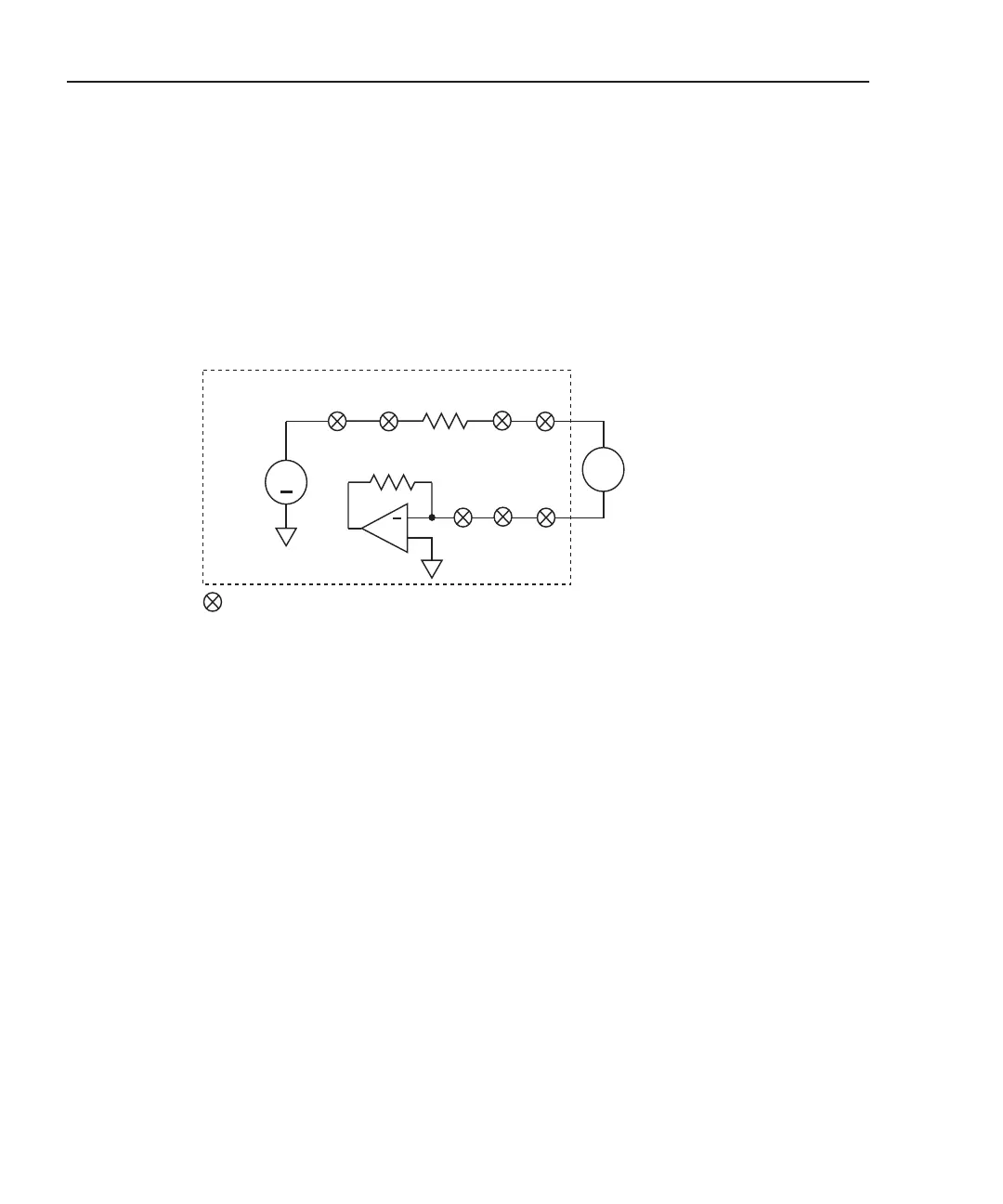
V-source readback
Test circuit
The V-source readback circuit is shown in Figure 5-11. Closing channels 13, 18, 21, 22,
and 23 routes the voltage to the DMM of the Model 2790. The DMM needs to be on the
1000V range to measure the maximum output of the 7751/7753 (500V).
Figure 5-11
V-source readback circuit
2790 DMM
Input Hi
V
SOURCE
+
22
v
Input Lo
18
18
= Closed channel switch
13
13
21
23
+
Selects
V-source
I/V
Amplifier
1Ω
NOTE Each channel (except channel 23) is a 2-pole switch. Therefore,
when a 2-pole channel is closed, two switches close. Channel 23
is a 1-pole switch (see schematic in Figure 2-1).
Open switches not used in the test circuit are not shown.
Keithley 7751/7753
 Loading...
