Interactive SourceMeter® Instrument User's Manual Section 7: Measuring I-
V characteristics of FETs
2450-900-01 Rev. C / December 2013 7-3
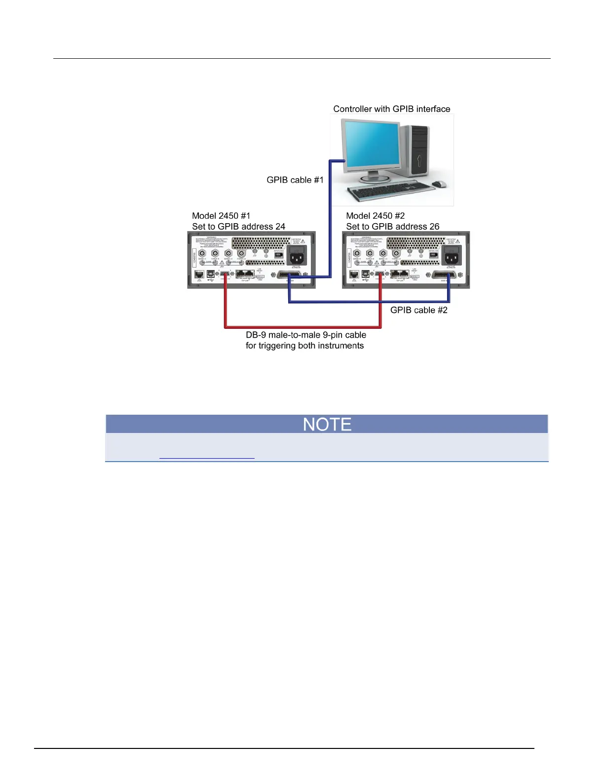
Figure 30: GPIB and DB-9 cable connections for the SCPI programming example
The figure above also shows the communication cable connections if you are using the GPIB remote
communication interface. GPIB cable #1 connects the GPIB port on the computer (controller) to the
IEEE-488 connector on the rear panel of Model 2450 #1. GPIB cable #2 connects the IEEE-488
connectors of the two Model 2450s.
Each Model 2450 must have a different GPIB address. You can set this up using the front panel. For
details, see Set the GPIB address (on page 3-3).
If you are using USB cables to connect the computer and Model 2450 instruments, each instrument
must be connected to the computer with a separate USB cable.
If you are using ethernet connections to connect the computer and Model 2450 instruments, the
instruments and computer must be connected using an ethernet switch or hub.
Connections for the TSP command set
If you use the Test Script Processor (TSP
®
) command set for remote programming, use a Model
CA-180-3A crossover cable (one is included with the Model 2450) to connect the TSP-Link ports on
the rear panels of the Model 2450 instruments to each other (see figure below). For more information
about using TSP-Link, see "TSP-Link System Expansion Interface" in the Model 2450 Reference
Manual.

 Loading...


