Interactive SourceMeter® Instrument User's Manual Section 7: Measuring I-
V characteristics of FETs
2450-900-01 Rev. C / December 2013 7-5
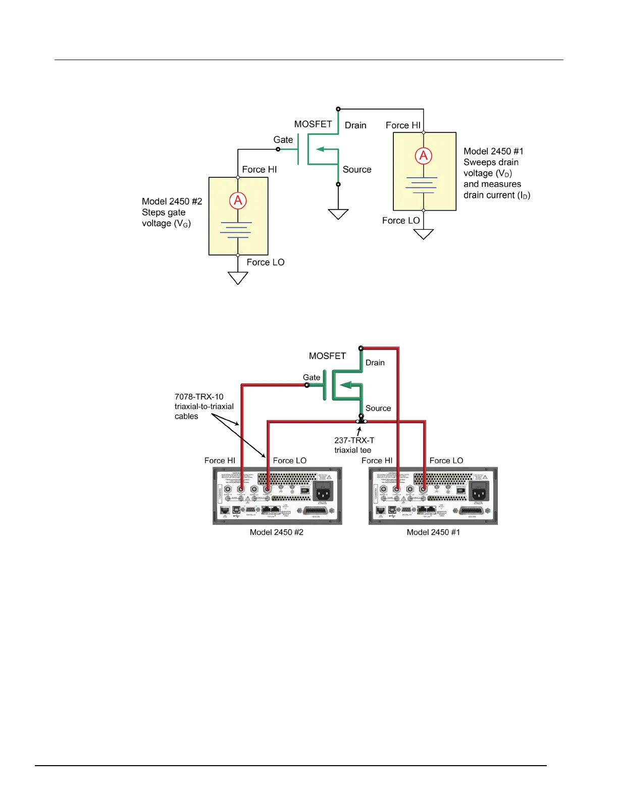
Figure 32: Three-terminal I-V test configuration for a MOSFET
The following figure shows the connections from the rear-panel terminals of both Model 2450
instruments to the MOSFET.
Figure 33: Two Model 2450s configured to test a three-terminal MOSFET
For this application, connect four triaxial cables (Model 7078-TRX-10) from the Model 2450
rear-panel female triaxial connectors to the MOSFET device. Mount the MOSFET device in a metal-
shielded test fixture with female triaxial connectors. Connect the Force LO terminals of both Model
2450 instruments to the Source terminal of the MOSFET using a triaxial tee connector (Model 237-
TRX-T).
Remote control of FET testing using SCPI commands
The two example sequences of SCPI commands for this application generate a drain family of curves
on a MOSFET using two Model 2450 instruments. One of the examples uses the trigger model to
generate the family of curves. The other example uses a linear sweep. You may need to make
modifications for operation in your programming environment.

 Loading...


