Appendix B: Kelvin (4W) S530 system diagnostics S530 Diagnostic Manual
1. If the current row is A and B:
Use pin 1 to connect the force and sense terminals of the current SMU under test to row A.
Use pin 2 to connect the force and sense terminals of the support SMU (except GNDU) to row B.
Use pin 3 to connect the force and sense terminals of the common lo (GNDU) to row C.
Use the current row (A or B) on the sense card to connect the current SMU under test and the
test support SMU together.
2. The last row pair is A and B with a Model 2410, and E and F without a Model 2410.
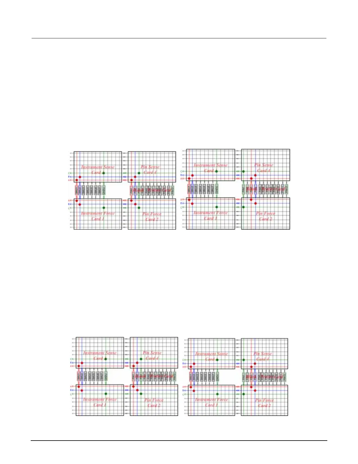
For the Model 2410 on row C, pin 3 or pin 1 will be connected to GNDU (see next Figure).
Figure 59: Model 2410, row C, pin 1 or 3
3. If the current row is C, D, E, and F:
Use pin 1 to connect the force and sense terminals of the current SMU to row C.
Use pin 2 to connect the force and sense terminals of the support SMU (except GNDU) with row
D.
Use pin 3 to connect the force and sense terminals of the common lo (GNDU) with row E.
Use the current row (C, D, E, or F) on the sense card to connect the SMU under test and the test
support SMU together.
For systems without a Model 2410, rows C or H and pin 1 or pin 3 will be connected to GNDU (see
next Figure).
Figure 60: Model 2410, rows C or H, pin 1 or 3
3-18 S530-906-01 Rev. A / March 2011
 Loading...


