3: LPTLib command reference S530/S540 KTE Linear Parametric Test Library (LPTLib) User's Manual
3-18 S530-900-01 Rev. E / September 2017
Example
double res1[14], res2[14];
.
conpin(SMU1, 1, 0);
conpin(SMU2, 2, 0);
conpin(GND, 3, 0);
forcev(SMU1, 4.0); /* Apply 4 V to gate. */
smeasi(SMU2, res1); /* Measure drain current in */
/* each step; store results */
/* in res1 array. */
sweepv(SMU2, 0.0, 14.0, 13, 2.0E-2); /* Make */
/* 14 measurements */
/* over a range of 0 V to 14 V. */
clrscn(); /* Clear smeasi. */
forcev(SMU1, 5.0); /* Apply 5 V to gate. */
smeasi(SMU2, res2); /* Measure drain current in */
/* each step; store results in */
/* res2 array. */
sweepv(SMU2, 0.0, 14.0, 13, 2.0E-2); /* Perform */
/*14 measurements */
/* over a range 0 V through 14 V. */
In this example, the sweepX command configures SMU2 to source a voltage that sweeps from 0 V through
+14 V in 14 steps. The results of the first sweepv command are stored in an array called res1. Because
of the clrscn command, the data and pointers associated with the first sweepv command are cleared.
Then 5 V is forced to the gate, and the measurement process is repeated. Results from these second
measurements are stored in an array called res2.
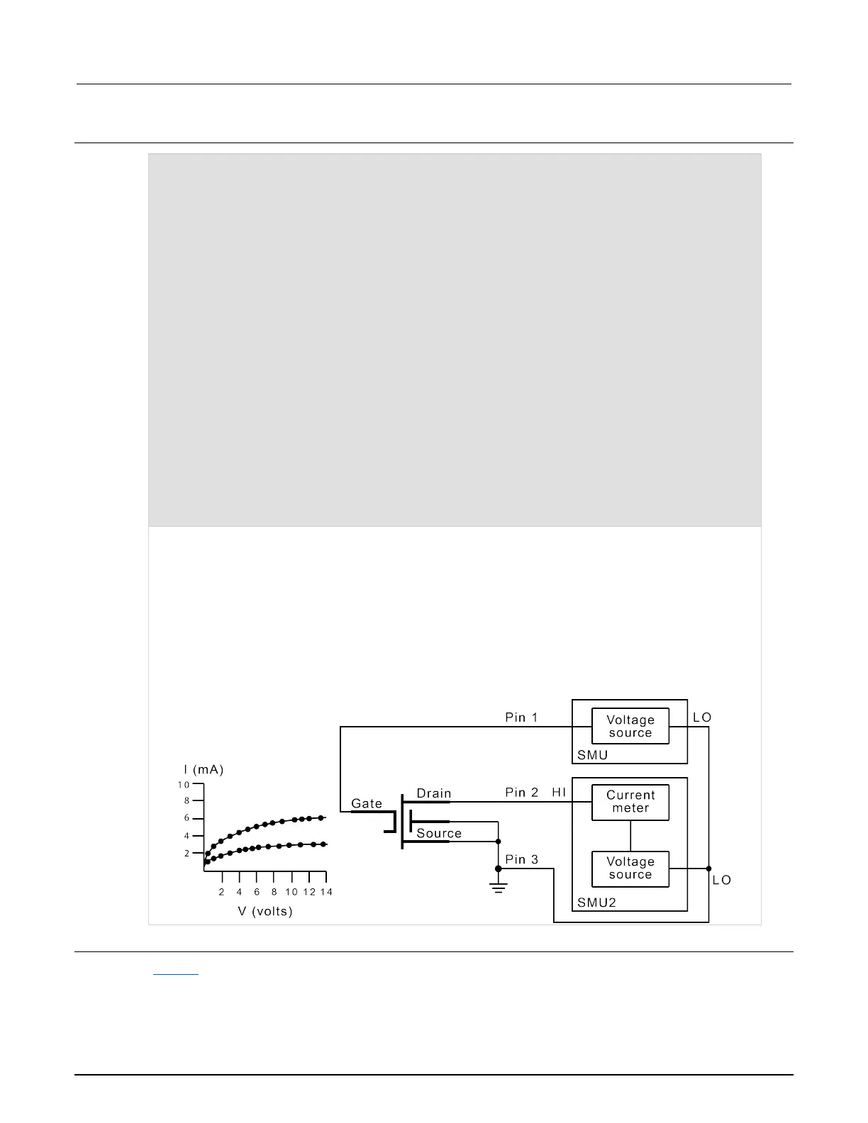
This example gets the measurement data needed to create a graph showing the gate voltage-to-drain
current characteristics of a field-effect transistor (FET). The program samples the current generated by
SMU2 14 times. This is done in two phases: First with 4 V applied to the gate, and then with 5 V applied.
The gate voltages are generated by SMU1.
Figure 1: S530/S540 gate voltage-to-drain current characteristics
Also see
sweepX (on page 3-88)