62 KXS_KXG-TM-BA_IA-e-1932
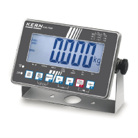
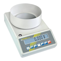
15 Installing display unit / weighing bridge
Installation / configuration of a weighing system must be carried out by a well
acquainted specialist with the workings of weighing balances.
15.1 Technical data
Supply voltage 5 V/150mA
Max. signal voltage 0-10 mV
Zeroing range 0-2 mV
Sensitivity 2-3 mV/V
Resistance parameter 80 - 100 Ω, max 4 items per 350 Ω load cell
15.2 Weighing system design
The display unit is suitable for connection to any analogue load cell in compliance
with the required specifications.
The following data must be established before selecting a load cell:
• Weighing balance capacity
This usually corresponds to the heaviest load to be weighed.
• Preload
This corresponds to the total weight of all parts that are to be placed on the
weighing cell such as upper part of platform, weighing pan etc.
• Total zero setting range
This is composed of the start-up zero setting range (± 2%) and the zero
setting range available to the user via the ZERO-key (2%). The total zero
setting range equals therefore 4 % of the scale’s capacity.
The addition of weighing scales capacity, preload and the total zero setting
range give the required capacity for the weighing cell.
To avoid overloading of the weighing cell, include an additional safety
margin.
• Smallest desired display division
• Verifiable, if required
 Loading...