TP-5867 11/02 23Section 4 Controller Troubleshooting
Section 4 Controller Troubleshooting
4.1 Relay Controller
This section covers controller troubleshooting
procedures for 8.5/11RMY generator sets equipped
with relay controllers and related engine components.
Refer to the generator set Operation Manual for
operating instructions. Refer to Figure 4-2 or Figure 4-3
to identify the controller internal components. Some
controllers use a different circuit breaker than the one
shown in Figure 4-2. The integrated controllers shown
in Figure 4-3 have the cyclic crank circuits integrated
into the main circuit board and have a fault lamp on the
front face.
Controller
Model No. Spec. No.
Basic
358076
Integrated
GM10615
8.5RMY PA-195021 X
PA-195025 X
GM16902-GA1 X
GM24829-GA1 X
11RMY PA-195022 X
PA-195026 X
GM16902-GA2 X
GM24829-GA2 X
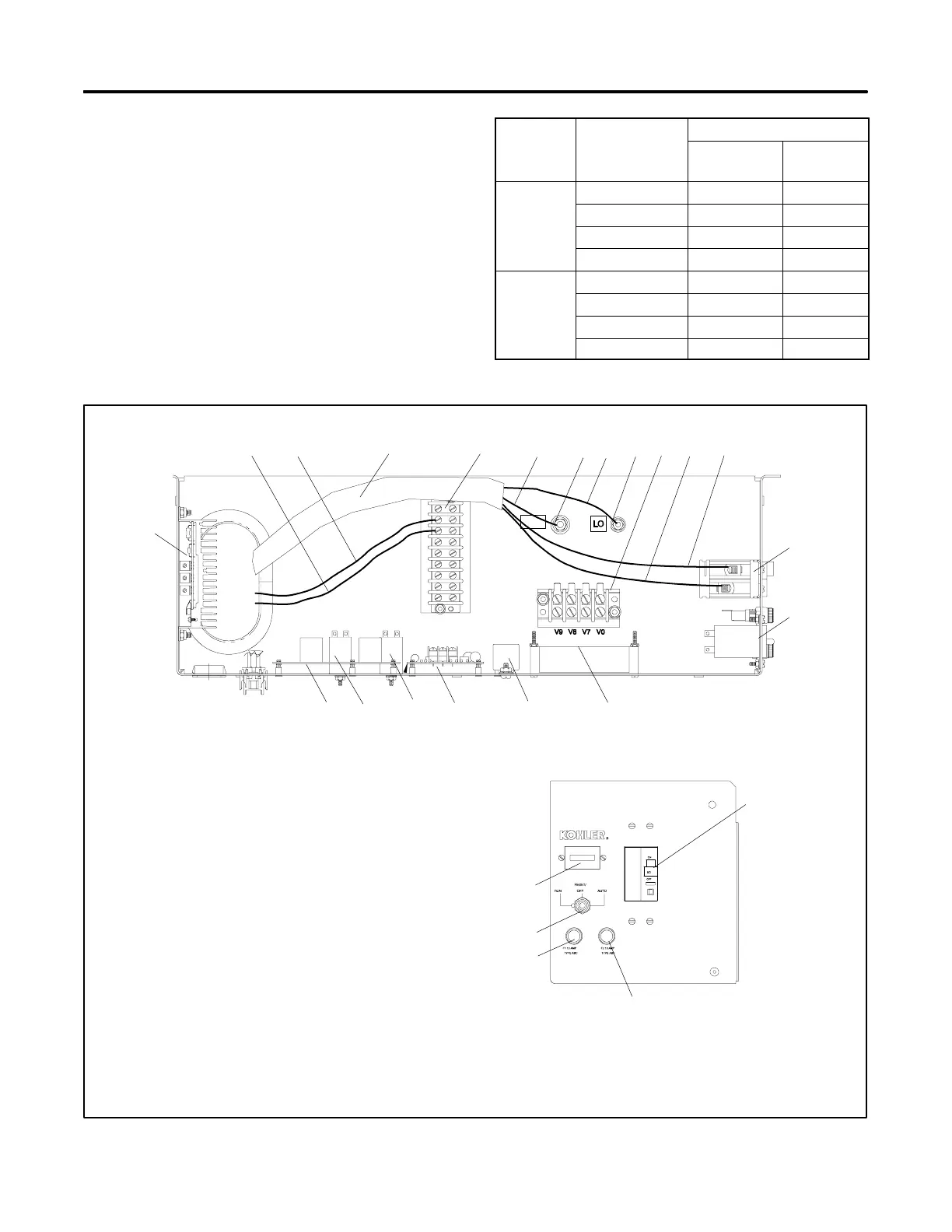
Figure 4-1 Generator Set Controllers
A-358076-L
GRD
6868
6767
FPFP
FNFN
7070
7N7N
3
4
3232
1. Remote start lead 3
2. Remote start lead 4
3. AC load leads
4. TB1 interconnect terminal block
5. Ground lead GND
6. Ground (GRD) terminal
7. Neutral lead L0
8. Neutral (L0) terminal
9. TB2 AC terminal block
10. Load lead L1
11. Load lead L2
12. Circuit breaker (type may vary)
13. Hourmeter
14. Electronic governor circuit board
15. Control power relay (K25)
16. Cyclic cranking circuit board
17. Cyclic cranking relay (K21)
18. Ignition relay (K5)
19. Controller circuit board
20. Voltage regulator
21. Voltage regulator fuse (10 amp)
22. Controller fuse (10 amp)
23. Generator set master switch
Top V ie w
Front View
20
469
12
13
14
19 15161718
8
13
23
22
21
12
231761011
Figure 4-2 Basic Relay Controller 358076 with Separate Cyclic Crank Board (shows field-installed wiring)
 Loading...


