TP-5867 11/0238 Section 6 Component Testing and Adjustment
6.3.2 Voltage Regulator Adjustment
The factory sets the voltage regulator for correct
generator operation under a variety of load conditions.
Usually, the voltage regulator needs no further
adjustment. Adjust the regulator according to the
following procedure after voltage reconnection or if the
regulator has been tampered with or replaced.
The voltage adjustment procedure uses three
potentiometers located on the voltage regulator. See
Figure 6-4 and Figure 6-7. The procedure also requires
a meter that can measure voltage and frequency.
Voltage Adjustment Potentiometer Adjusts
generator output between 100 and 130 volts.
Stabilizer Potentiometer Fine tunes regulator circuitry
to reduce light flicker.
Volts/Hz Potentiometer Determines frequency (Hz) at
which generator output voltage begins to drop.
Note: In applications requiring fine voltage adjustment,
connect a 10 kOhm, 1/2 watt minimum rheostat
(customer-provided) across terminals 33 and 66
on the PowerBoostäIIIE voltage regulator. See
Figure 6-6. The rheostat provides a 5-volt
adjustment range.
+--
4
3
33
44
21
55
GY
R
YO
W
BK
66
44 33
55 --
+
66
1
23 4
5
6
8
7
9
10
11
13
TP563277
4
3
33
12
1. Remote rheostat (customer-provided)
2. Voltage adjustment potentiometer
3. Stabilizer potentiometer
4. Volts/Hz potentiometer
5. Stator/rotor connections (for reference only)
6. Lead color
7. DC output
8. Main field (rotor)
9. 5-amp fuse
10. Sensing leads (33-44)
11. AC power input (auxiliary) lead (55)
12. Main leads (1 --2, 3 --4)
13. Stator
12
Figure 6-6 PowerBoostäIIIE Voltage Regulator Test
and Adjustment Setup
A-358076
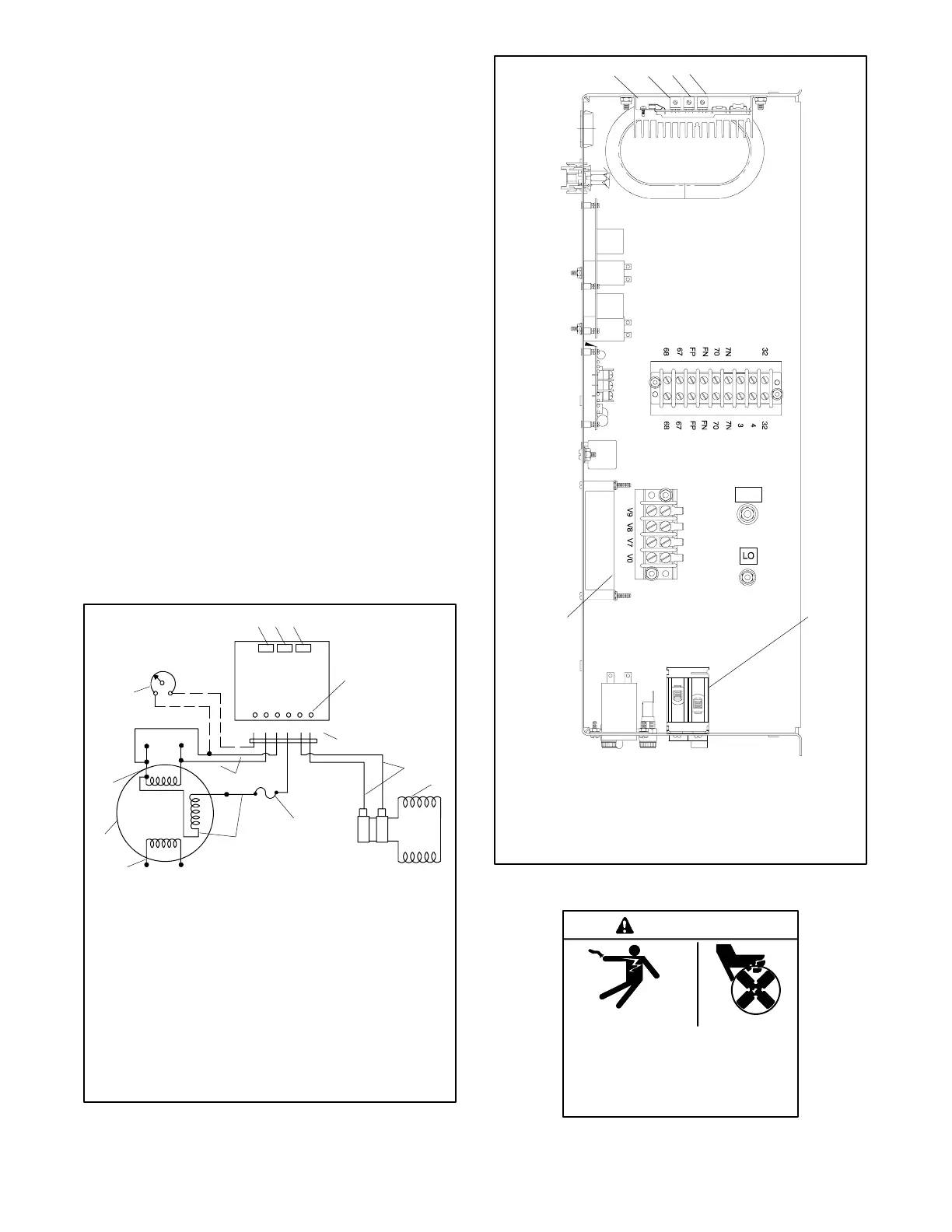
1
6
6868
6767
FPFP
FNFN
7070
7N7N
3
4
3232
GRD
324
1. Voltage regulator
2. V/Hz potentiometer
3. Stabilizer potentiometer
4. Voltage adjustment potentiometer
5. Circuit breaker
6. Governor circuit board
5
Figure 6-7 Controller Top View, Typical
Hazardous voltage.
Can cause severe injury or death.
Operate the generator set only when
all guards and electrical enclosures
areinplace.
Moving rotor.
WARNING
 Loading...


