TP-5867 11/0236 Section 6 Component Testing and Adjustment
Grounding electrical equipment. Hazardous voltage can
cause severe injury or death. Electrocution is possible
whenever electricity is present. Open the main circuit
breakers of all power sources before servicing the equipment.
Configure the installation to electrically ground the generator
set, transfer switch, and related equipment and electrical
circuits to comply with applicable codes and standards. Never
contact electrical leads or appliances when standing in water
or on wet ground because these conditions increase the risk of
electrocution.
Short circuits. Hazardous voltage/current can cause
severe injury or death. Short circuits can cause bodily injury
and/or equipment damage. Do not contact electrical
connections with tools or jewelry while making adjustments or
repairs. Remove all jewelry before servicing the equipment.
Separate Excitation Procedure
Perform the following procedure to use an external
voltage source to excite the main field (rotor).
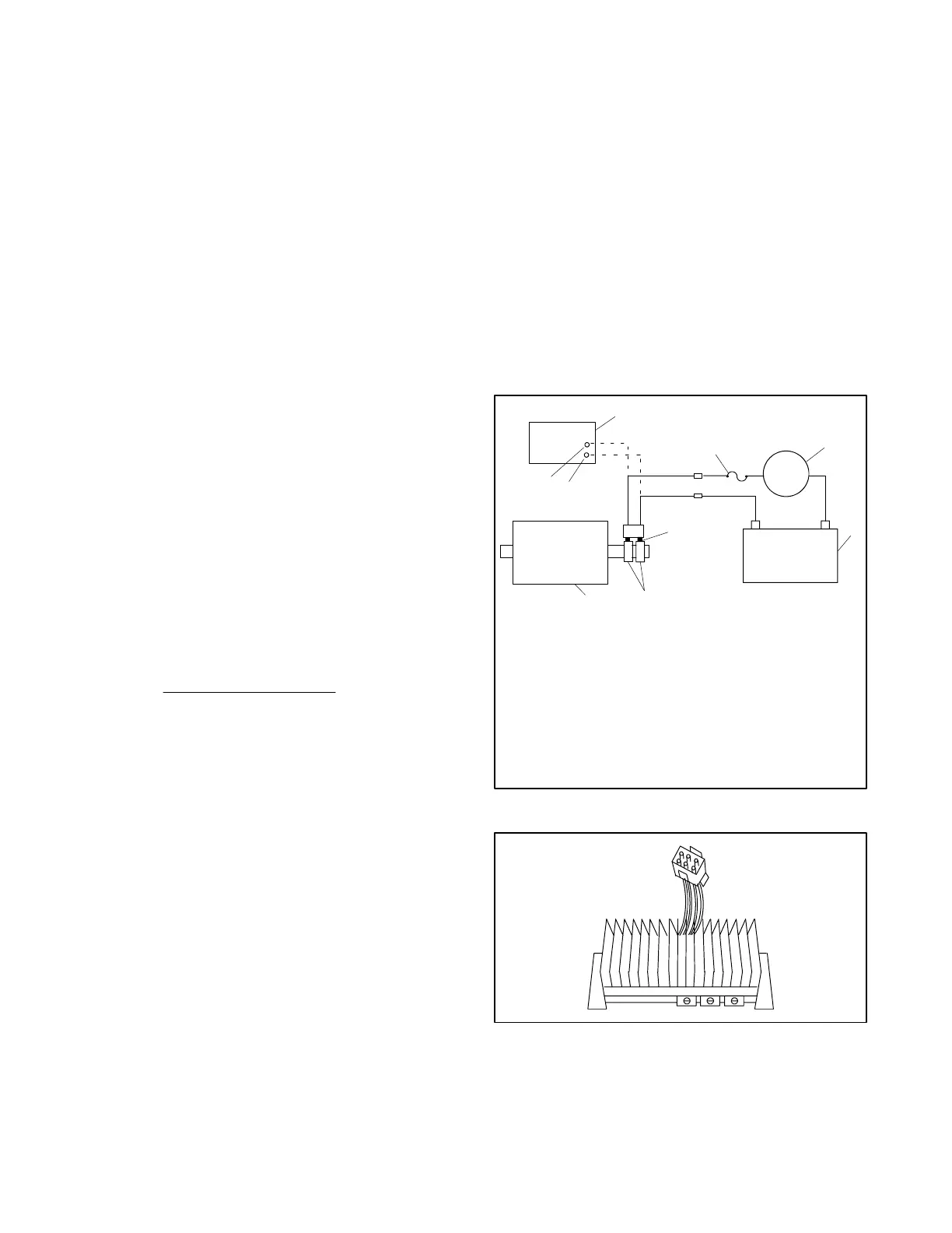
1. Disconnect the six pin connector from the voltage
regulator.
2. Connect a DC ammeter, 10-amp fuse, and a
12-volt automotive battery to the positive (+) and
negative (--) brush leads as shown in Figure 6-3.
Note and record the ammeter reading.
Note: The approximate ammeter reading should
be the battery voltage divided by the
specified rotor resistance.
Example:
12 volts (battery voltage)
4 ohms (rotor resistance)
=
3amps
(rotor current)
Note: See Section 1, Specifications, for specified
rotor resistance values.
3. Start the engine and check that the ammeter
reading remains stable. An increasing meter
reading indicates a shorted rotor. A meter reading
decreasing to zero or an unstable reading
suggests a running open. Refer to Section 6.4.2,
Main Field (Rotor), to test the rotor. If the ammeter
reading is stable, proceed to step 4.
4. Check for AC output across the stator leads; see
Section 6.5, Stator. Compare the readings to the
AC output values shown in Section 1,
Specifications. If the readings vary considerably, a
faulty stator is likely. Refer to Section 6.5, Stator,
for further information.
5. If this test shows that the rotor and stator are in
good condition, check the voltage regulator. See
Section 6.3, Voltage Regulator.
6.3 Voltage Regulator
Single-phase generator sets use the Power-BoosttIIIE
voltage regulator. See Figure 6-4.
The PowerBoostäIIIE voltage regulator monitors
generator output voltage and provides excitation current
to the rotor. PowerBoostäIIIE maintains generator
output at the specified voltage under load until the
generator engine speed drops to a preset level (factory
setting 57.5 Hz on 60 Hz models and 47.5 Hz on 50 Hz
models). Then the regulator allows the generator
voltage and current to drop. The voltage/current drop
enables the engine to pick up the load. When the
generator speed returns to normal (60 Hz or 50 Hz) as
load is accepted, the generator output also returns to
normal.
+
-
+
3
1
2
4
5
6
7
8
9
TP563274
-
1. (--) Terminal—1-phase (12) Terminal—3-phase
2. (+) Terminal—1-phase (10) Terminal—3-phase
3. Voltage regulator
4. 10-amp fuse
5. DC ammeter
6. 12V battery
7. Brushes
8. Slip rings
9. Main field (rotor)
Figure 6-3 Separate Excitation Connections
TP563275
Figure 6-4 PowerBoostäIIIE Voltage Regulator
 Loading...


