TP-5867 11/0224 Section 4 Controller Troubleshooting
GR
D
6868
6767
FPFP
FNFN
7070
7N7N
33
44
3232
L2
L1
3
4
GM10615
Top V ie w
Front View
8
12
4
5
6
7
3
5
12
11
10
4
AUTOOFF
RESET/
RUN
R
F2 10 AMP
TYPE ABCTYPE ABC
F1 10 AMP
40
ON
OFF
FAULT
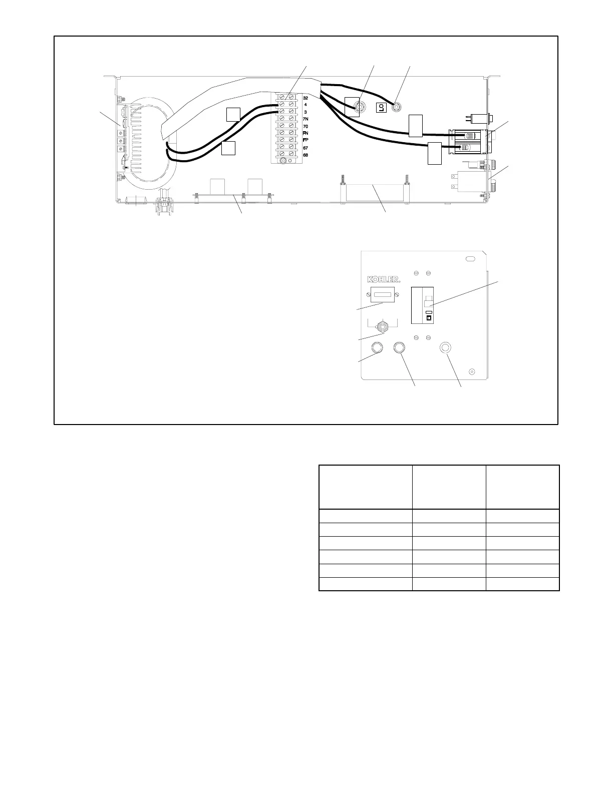
1. TB1 interconnect terminal block
2. Ground (GRD) terminal
3. Neutral (L0) terminal
4. Circuit breaker
5. Hourmeter
6. Electronic governor circuit board
7. Controller circuit board (includes cyclic crank controls)
8. Voltage regulator
9. Fault lamp
10. Voltage regulator fuse (10 amp)
11. Controller fuse (10 amp)
12. Generator set master switch
9
Figure 4-3 Integrated Relay Controller GM10615 with Fault Lamp and Cyclic Crank Control (shows
field-installed wiring)
4.2 Sequence of Operation
The following sections describe the controller sequence
of operation during generator start, run, stop, and fault
shutdown modes. Use this as a starting point for
controller fault identification. Use the LEDs on the
controller circuit board to assist in the troubleshooting
process. Refer to the wiring diagrams in Section 9 to
assist in the troubleshooting procedure.
An illuminated LED indicates that the corresponding
relay is receiving power; the LED does not indicate
whether the relay is functioning. The relays on the
controller circuit board are not replaceable. Replace the
circuit board if one or more relays are faulty.
Identify the circuit board installed in the controller by the
number printed on the edge of the board. Then see
Figure 4-4 through Figure 4-7 for relay descriptions and
locations.
Relay Description
Basic Relay
Controller
(Figure 4-2)
Integrated
Relay
Controller
(Figure 4-3)
External Fault Latch K5 K1
Fault Shutdown K1 K2
Start/Run K2 K3
Crank Disconnect K3 K4
Crank/Flash K4 K5
Ignition Kill — K6
Figure 4-4 Controller Circuit Board Relays
 Loading...


