TP-5867 11/02 51Section 6 Component Testing and Adjustment
6.10 Speed Sensor
Use the following test procedure to verify that the speed
sensor operates correctly.
Speed Sensor Test Procedure
1. Place the generator set master switch in the OFF
position.
2. Disconnect power to the battery charger, if
equipped.
3. Disconnect the generator set engine starting
battery, negative (--) lead first.
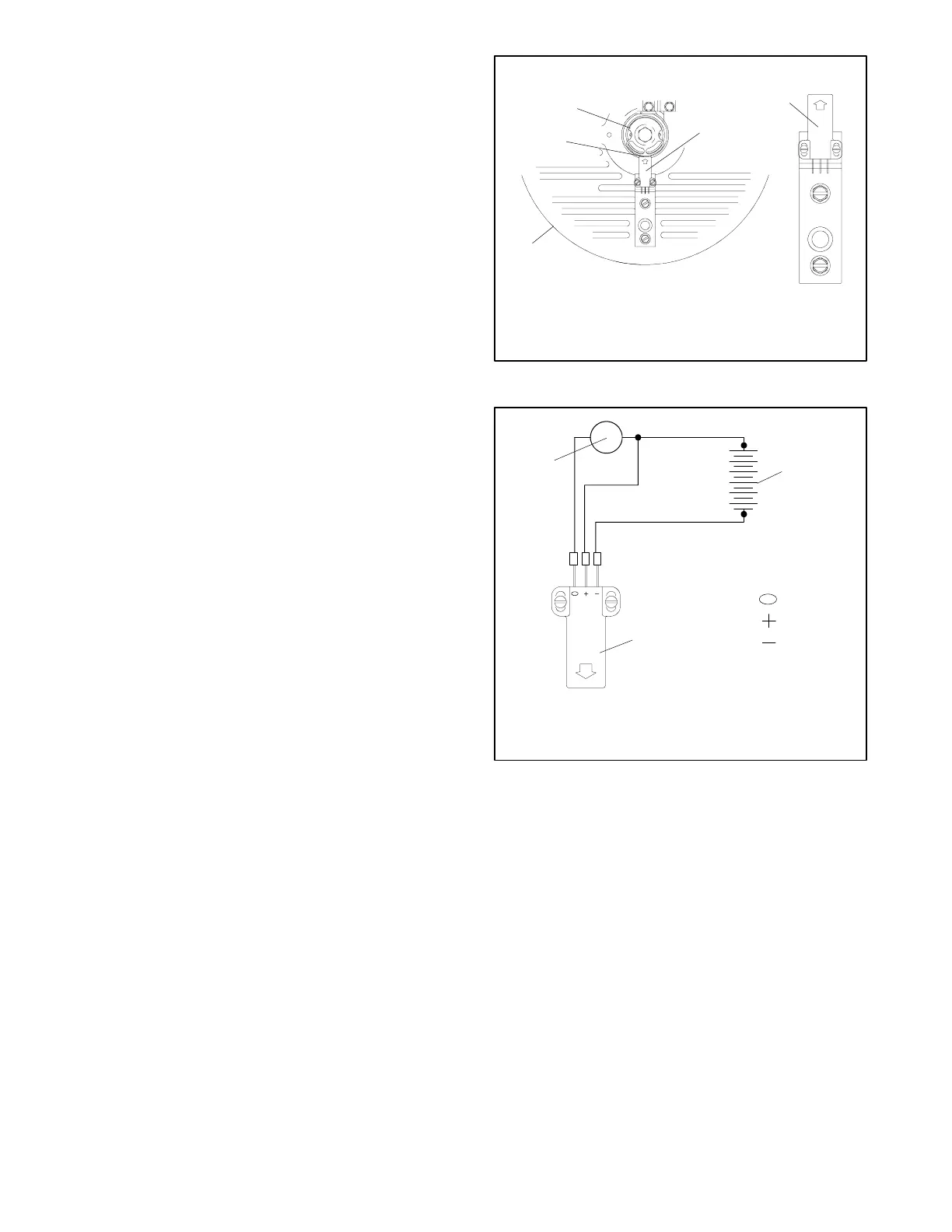
4. Remove the speed sensor from the alternator end
bracket. See Figure 6-22.
5. Connect the speed sensor, voltmeter, and DC
voltage source as shown in Figure 6-23.
6. Touch the sensing surface with a flat piece of iron or
steel. The contact surface area of the iron or steel
piece should be at least 4 sq. cm (1/4 sq. in.). The
voltmeter reading should equal the source voltage.
7. Remove the iron or steel from the sensing surface.
The voltmeter should indicate no voltage.
8. Reinstall the speed sensor onto the end bracket
using all original hardware. See Figure 6-22. Set
the air gap between the speed sensor and magnetic
actuator to 0.25--0.51 mm (0.010--0.020 in.).
9. Check that the generator set master switch is in the
OFF position.
10. Reconnect the generator set engine starting
battery, negative (--) lead last.
11. Reconnect power to the battery charger, if
equipped.
A-358000B-C
3
2
1
2
4
1. Magnetic actuator
2. Speed sensor
3. End bracket
4. Air gap
Figure 6-22 Speed Sensor Air Gap
+
+
--
1
2
3
5632726
Red
White
Black
1. DC voltmeter
2. 12-volt DC power supply
3. Speed sensor sensing surface
Figure 6-23 Speed Sensor Test Connections
 Loading...


