TP-5867 11/0228 Section 4 Controller Troubleshooting
4.4 Cyclic Cranking
The cyclic cranking adjustment potentiometers located
in the controller allow adjustment of the cranking cycle
for improved starter motor engagement. The basic
controller has a separate cyclic cranking circuit board.
See Figure 4-10. The integrated controller has the
adjustment potentiometers mounted on the controller
circuit board. See Figure 4-11.
The factory sets the cranking cycle for eight seconds on
time and three seconds off time. If the cranking cycle
seems shorter than the factory setting, check the engine
starting battery before readjusting the potentiometers.
The timing decreases if the battery charge is too low.
+
--
2
1
3
4
C-284507-C
1. On potentiometer
2. Off potentiometer
3. Battery
4. Voltmeter
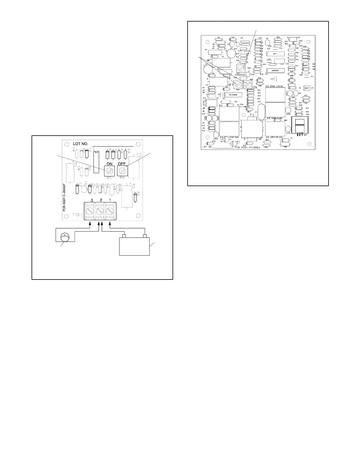
Figure 4-10 Cyclic Cranking Board Test Connections
GM10064-
1. Overspeed adjustment potentiometer, R17
2. Cyclic crank potentiometers
1
2
Figure 4-11 Integrated Controller Circuit Board Cyclic
Crank Potentiometer Location
4.4.1 Adjustment
The ON and OFF potentiometers allow adjustment of
the on and off cycles from 1 to 60 seconds. See
Figure 4-10 or Figure 4-11. If the generator set engine
does not perform the cyclic crank routine during starting,
verify that the cyclic cranking is correctly adjusted.
Rotate the corresponding potentiometer clockwise (cw)
to increase the time period or counterclockwise (ccw) to
decrease it. The cyclic crank feature does not operate
when both potentiometers are in the full ccw position.
4.4.2 Testing
The cyclic cranking board in the basic controller can be
removed and tested on the bench. If the cyclic crank
circuit board is correctly adjusted but the engine does
not go through the preferred crank cycle, test the board
using the following cyclic crank board test procedure.
Test equipment needed:
D 12-volt battery or DC power supply
D DC voltmeter
 Loading...


