TP-6774 2/14a 55Section 7 Controller
7.6 Communication Port
The main logic circuit board contains a standard type B
USB communication port for PC connections and a USB
host connector for a mass-storage device connection.
See Figure 7-9 and Figure 7-10. See Section 7.13.12 for
USB flowchart information. Refer to the List of Related
Materials in the Introduction for corresponding SiteTecht
software and/or communication installation information.
Note: Before inserting a mass-storage device (USB host
connector), power off and then power on the
controller.
See Figure 7-8 for tested/approved manufacturer’s
USB flash drive types that work with the ADC IId
controller.
CustomUSB
(Kohler Power Systems
Part Number KW-A202)
2-GB “spin” full size
Imation 4-GB full size
Lexar 4-GB full size
PNY 4-GB full size and micro
Verbatim 4-GB full size and micro
Figure 7-8 USB Types Tested/Approved for ADC IId
1. USB port cover
1
Figure 7-9 Communication Port
1 2
1. USB device connector (connects to SiteTech)
2. USB host connector (connects to mass-storage device)
Figure 7-10 ADC IId USB Identification
7.7 Fuses
Fuses are located on the side of the junction box. See
Figure 7-11.
D 10 -Amp (F1) fuse protects the auxiliary winding.
D 20 -Amp (F2) fuse protects the controller circuits, fuel
pump, and fuel shutoff solenoid.
D 5-Amp (F3) fuse protects the customer connections.
1. Fuses (qty. 3)
1
Figure 7-11 Fuses on the Side of the Junction Box
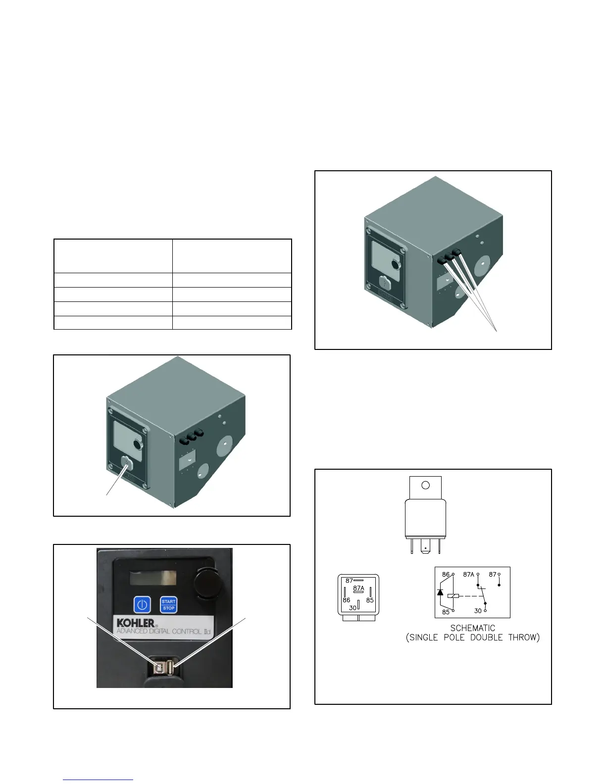
7.8 Preheat Relay
The junction box contains two preheat relays that power
the engine glow plugs. See Figure 7-1 for location. The
programmed glow plug circuit is for cold starting. See
Figure 7-12.
GM49746-P
Rated Voltage 12 VDC
Operating Current 133 mA
Coil Resistance 90 ± 10 ohms
Pull-In Voltage < 8 V
Release Voltage 1.2 V
Max. Operating Voltage 14.4 V
Figure 7-12 Preheat Relay Specs

 Loading...


