TP-6774 2/14a 89Section 8 Component Testing and Adjustment
Coolant Temperature Sensor (CTS)
The coolant temperature sensor (CTS) is used to
monitor engine temperature for the high engine
temperature fault shutdown. See Figure 8-26 for the
coolant temperature sensor location. Power down the
generator set and allow the generator set to cool.
Disconnect the CTS and use an ohmmeter to measure
the resistance across the sensor. The sensor
resistance varies with temperature and should be within
the values shown in Figure 8-27. If the resistance is very
low (indicated a short circuit) or very h igh (indicating an
open circuit) replace the CTS.
1
1. Coolant temperature sensor
Figure 8-26 Coolant Temperature Sensor Location
Temperature, _C(_F)
Resistance, Ohms
30 (86) 2106--2392
100 (212) 182--198
Figure 8-27 Coolant Temperature Sensor Resistance
Readings (All Models)
High Exhaust Temperature (HET) Switch
In the event of a shutdown because of high exhaust
temperature, the ADC IId controller will display fault
code Exh. Temp High Shutdown. See Figure 8-28 for
the high exhaust temperature switch location. High
exhaust temperature of 215_ ±5_ F (102_ ±2.8_ C) will
cause the unit to shut down.
1
1. High exhaust temperature switch
Figure 8-28 High Exhaust Temperature Switch
Location
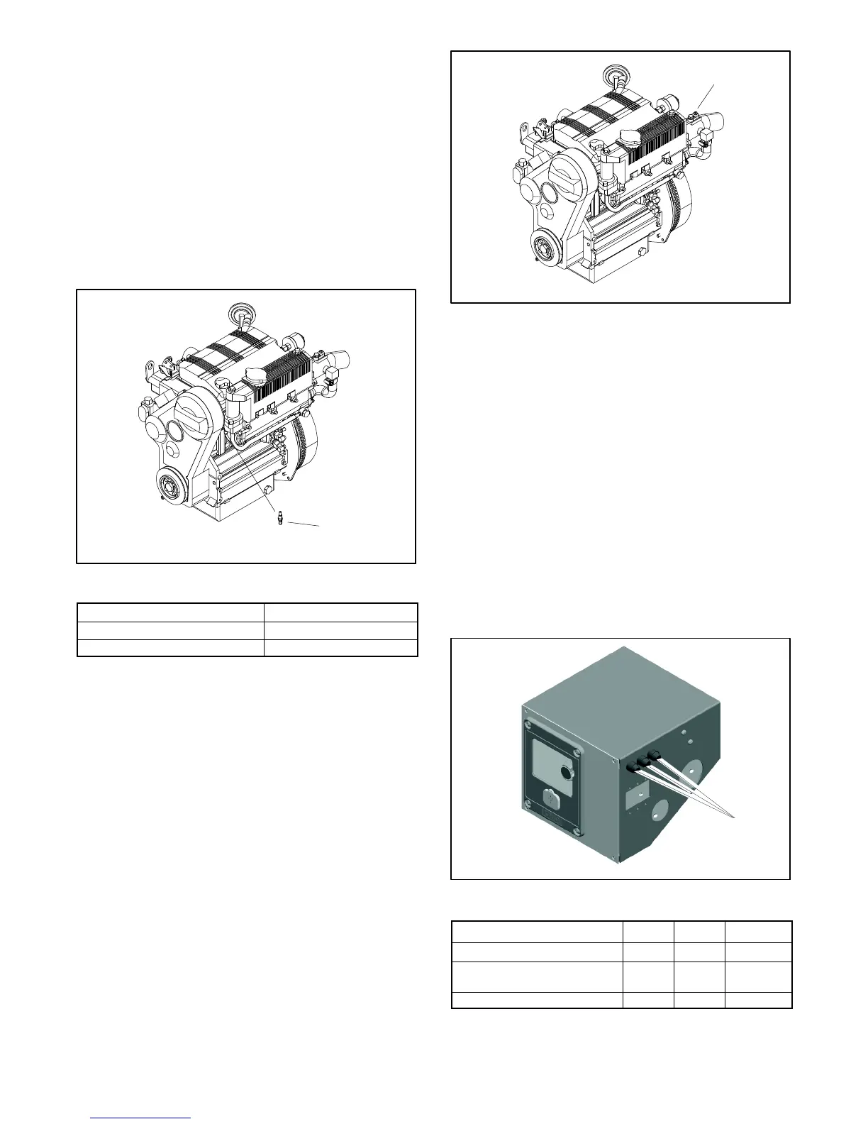
8.15 Fuses
Fuses are located on the side of the junction box. See
Figure 8-29. Always identify and correct the cause of a
blown fuse before restarting the generator set. Refer to
Section 6, Troubleshooting, for conditions that may
indicate a blown fuse. Replace blown fuses with
identical replacement parts.
D 10 -Amp (F1) fuse protects the auxiliary winding.
D 20 -Amp (F2) fuse protects the controller circuits, fuel
pump, and fuel shutoff solenoid.
D 5-Amp (F3) fuse protects the customer connections.
1. Fuses (qty. 3)
1
Figure 8-29 Fuses on the Side of the Control Box
Fuse Amps Label Part No.
Auxiliary Winding 10 F1 358337
Controller, Fuel Pump, and
Fuel Shutoff Solenoid
20 F2 GM39266
Customer Connection 5 F3 239298
Figure 8-30 Fuses

 Loading...


