TP-6774 2/14a78 Section 8 Component Testing and Adjustment
8.7 Rectifier Module (9--11EKOZD
and 7--9EFKOZD Models)
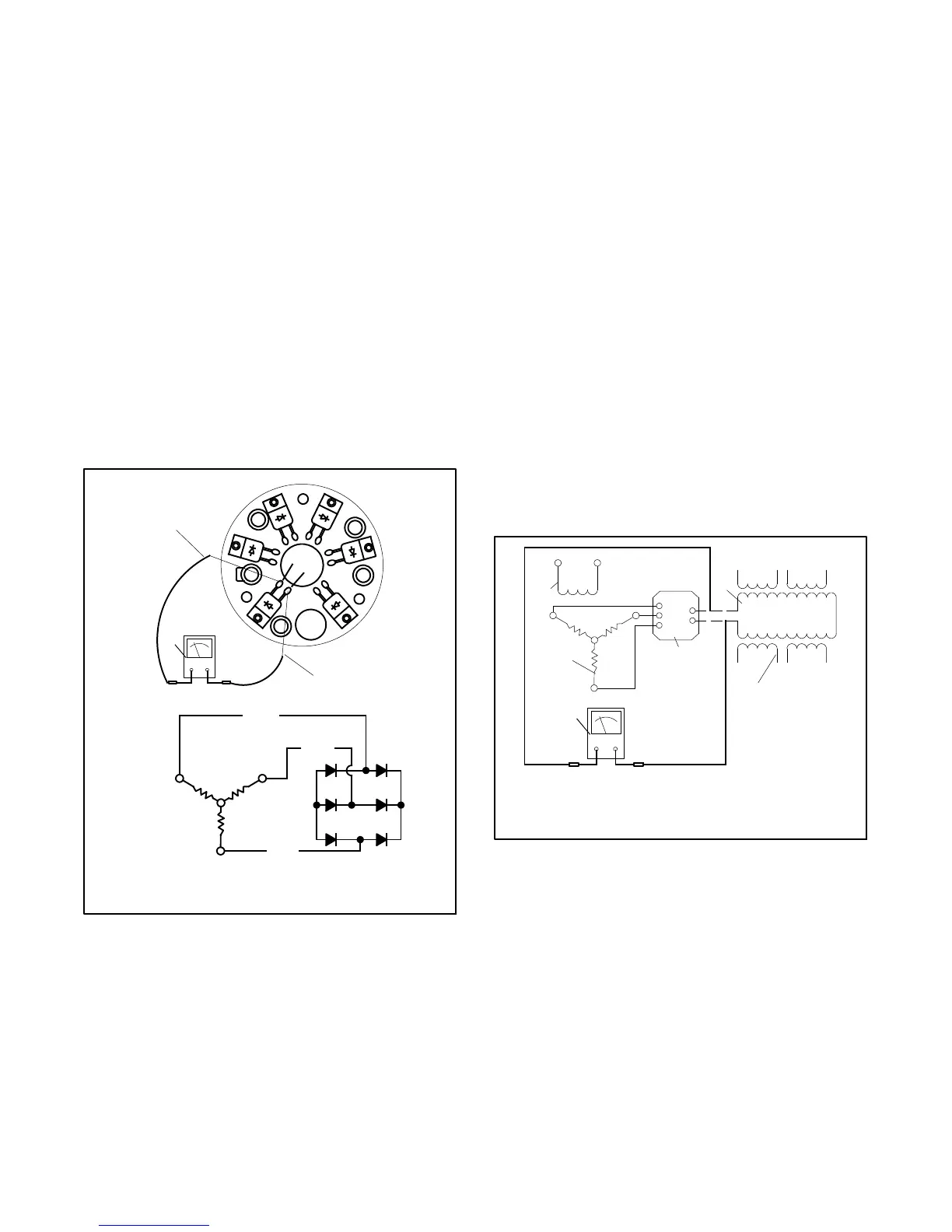
The rectifier module located between the exciter
armature and the main field converts AC from the exciter
armature to DC, which magnetizes the generator main
field. Test the rectifier module as described in the
following steps.
Rectifier Module Test Procedure:
1. Disconnect the exciter armature and the main field
leads from the rectifier module.
2. Use a n ohmmeter on the R x 100 scale to check the
resistance between all the rectifier diodes as
shown in Figure 8-9. The ohmmeter should show a
low resistance in one direction and, upon reversing
the ohmmeter leads, a high resistance in the other
direction. Replace the rectifier module if any of the
diodes tests differently than described.
A
B
C
--
+
1
2
TP-5983-7
3
1. Diode terminal
2. Diode terminal
3. Ohmmeter
A1
(AC)
(AC)
(AC)
C1
B1
B
C
+--
Figure 8-9 Rectifier Module Test
8.8 Rotor
The generator rotor (magnetized by DC from the rectifier
module) rotating within the stator windings induces AC
in the stator windings. Test the generator rotor (main
field) as described in the following steps. Disassemble
the generator prior to performing this test. See
Section 9.
Generator Main Field (Rotor) Test Procedure:
1. With the generator disassembled, disconnect the
generator main field windings at the rectifier
module terminals F+ and F--.
2. Check the main field resistance by connecting an
ohmmeter across the main field F+ and F-- leads.
See Figure 8-10. See Section 1, Specifications for
the resistance reading. A low reading indicates an
internal short and a high reading indicates an open
winding. Repair or replace the main field if the
ohmmeter readings indicate the main field is
inoperative. If the resistance test is inconclusive,
perform a megohmmeter test on the main field as
described in the next step.
F+
F--
AC
AC
AC
TP-5983-7
1
2
3
4
5
6
1. Main field (rotor)
2. Stator windings
3. Rectifier module
4. Ohmmeter
5. Armature
6. Exciter field
Figure 8-10 Ohmmeter Connections on
Main Field
3. Check the main field for a short-to-ground
condition by using a megohmmeter. Apply
500 volts DC to either field lead and the main field
frame. Follow the megohmmeter manufacturers
instructions for using the megohmmeter. See
Figure 8-11. A reading of 1.5 MOhms and higher
indicates the main field is functional. A reading of
less than 1.5 MOhms indicates deterioration of the
winding insulation and possible current flow to
ground; if so, replace the main field.

 Loading...


