TP-6774 2/14a 75Section 8 Component Testing and Adjustment
8.3 Exciter Field
(9--11EKOZD/7--9EFKOZD
Models)
Direct current from the battery magnetizes the exciter
field. When the exciter armature rotates within the
magnetized exciter field windings, an electrical current
develops within the exciter armature. Test the exciter
field according to the following procedure.
Exciter Field Test Procedure:
1. Press the start/stop button to stop the generator
set.
2. Press the power button to turn the controller off.
3. Disconnect the generator set engine starting
battery, negative (--) lead first.
4. Disconnect the FN/FP leads.
5. Check the exciter field resistance by connecting an
ohmmeter across exciter field FN and FP leads.
See Figure 8-4. See Section 1, Specifications for
the resistance reading of a cold exciter field. A low
reading indicates an internal short and a high
reading indicates an open winding. Repair or
replace the exciter field if the ohmmeter readings
indicate an inoperative exciter field (refer to
Section 9 for removal). If the resistance test is
inconclusive, perform a megohmmeter test on the
exciter field as described in the next step.
1
3
4
FN FP
TP-5983-7
2
1. ADC IId
2. Ohmmeter
3. Exciter field
4. Exciter armature
5. Main field (rotor)
5
Figure 8-4 Exciter Field Resistance Test
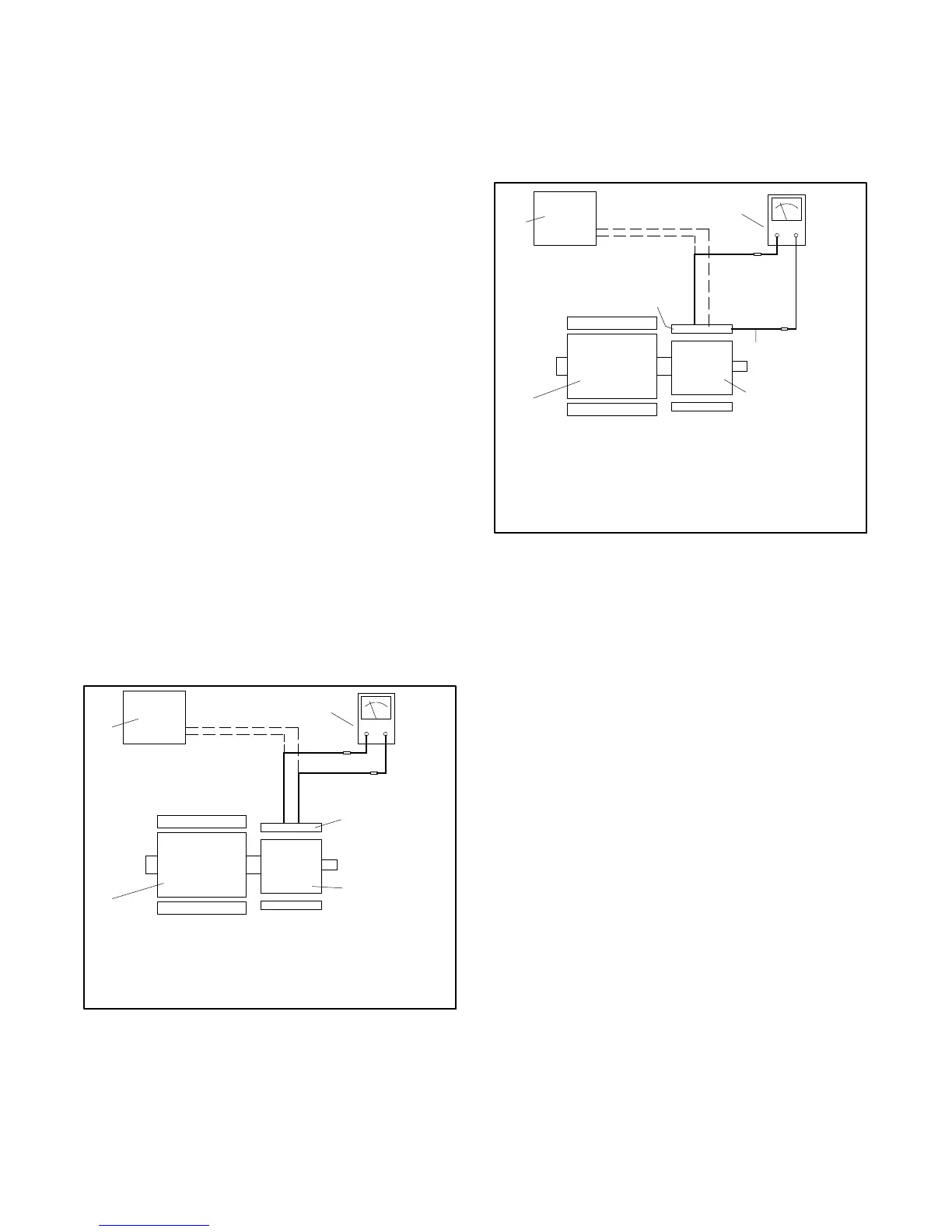
6. Check the exciter field for a short-to-ground
condition. Use a megohmmeter to apply 500 volts
DC to the FN or FP lead and the exciter field frame.
See Figure 8-5. Follow the megohmmeter
manufacturer’s instructions for using the
megohmmeter. A reading of approximately
1.5 MOhms and higher indicates the field winding
is functional. A reading of less than approximately
1.5 MOhms indicates deterioration of the winding
insulation and possible current flow to ground; if so,
replace the exciter field.
1
3
FN FP
4
5
TP-5983-7
2
1. ADC IId
2. Megohmmeter
3. Frame connection
4. Exciter armature
5. Exciter field
6. Main field (rotor)
6
Figure 8-5 Megohmmeter Connections on the
Exciter Field

 Loading...


