22 TP-6842 9/21
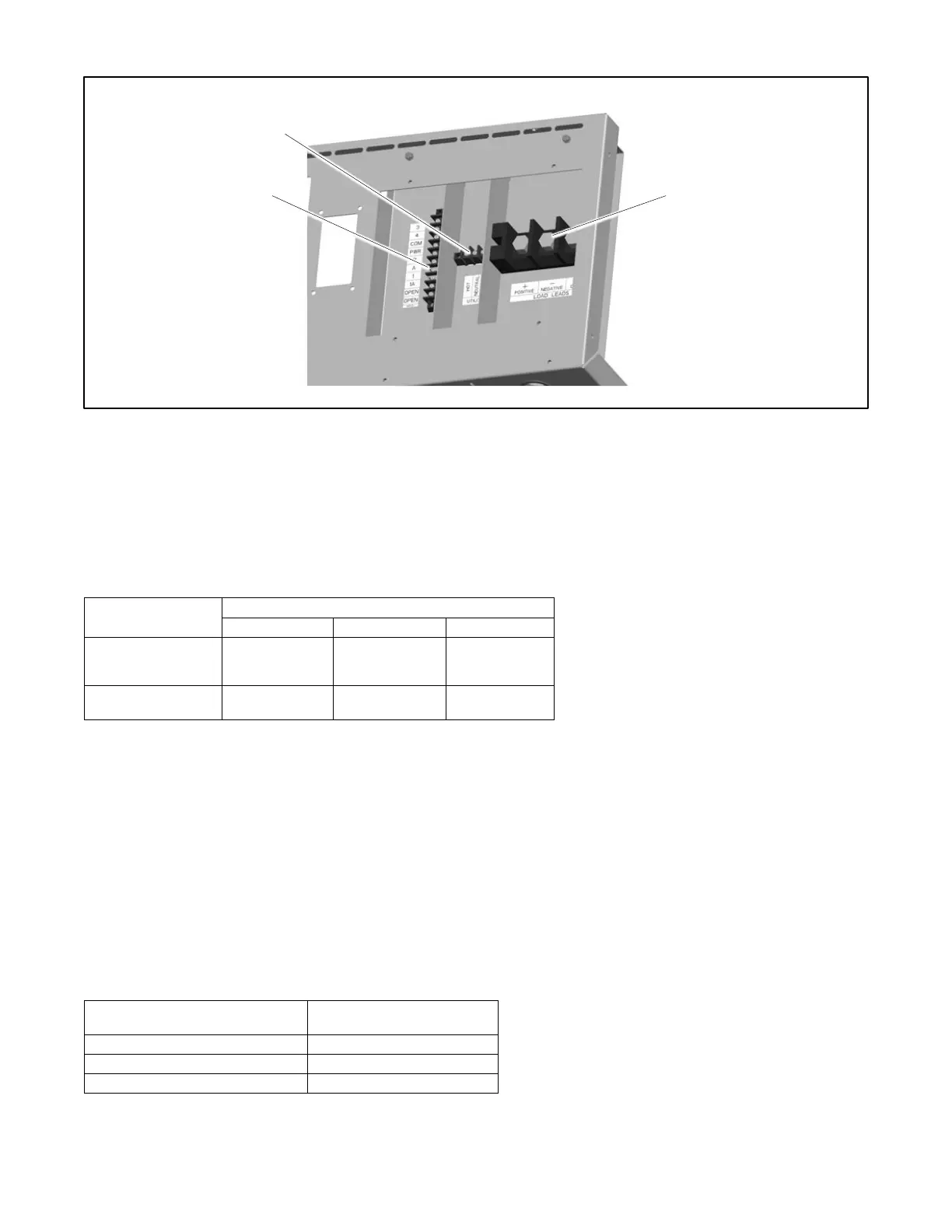
Figure 10 Electrical Connections
1.8.4 Power Supply
Provide AC power for the battery charger (integral to the VSC controller) and optional carburetor heater. The power requirements
are shown in Figure 11. The power source must be GFCI protected.
Be sure to disconnect power at the distribution panel before making the connections. Connect power leads to the utility power
connection points on the terminal block shown in the figure titled: Electrical Connections. See the section titled: Field-Connection
Terminal Block and the wiring diagrams in the Installation Drawings section for connection details.
Figure 11 Power Requirements
1.8.5 Programmable Interface Module (PIM) Connection
One programmable interface module can be connected to the generator set. Route low-voltage communication leads through
separate conduit. All connections must comply with applicable state and local codes.
See Figure 13. Use Belden #9402 or equivalent 20 AWG shielded, twisted-pair cable to connect P10-1 through P10-4 on the
programmable interface module (PIM) to the generator set terminal block TB1 connections A, B, PWR, and COM. Note the
shield connections shown in Figure 13. The maximum cable length using Belden #9402 cable is 61 m (200 ft.).
For outdoor installations, including those with buried cables and/or conduit, use outdoor-rated Belden #1075A or equivalent 20
AWG shielded, twisted-pair communication cable.
For longer cable runs, use Belden #8762 or equivalent 20 AWG shielded, twisted-pair cable with 2 conductors for the A and B
connections, and use 12-14 AWG wire for the COM and PWR connections. See Figure 12 for the maximum cable lengths.
 Loading...


