EasyManuals Logo
Home>Kohler>Portable Generator>6VSG

Kohler 6VSG Installation

Kohler 6VSG
48 pages
To Next Page IconTo Next Page
To Previous Page IconTo Previous Page
Page #24 background imageLoading...
Page #24 background image
24 TP-6842 9/21
Connection
PIM Settings
Input 1
None
Input 2
None
Output 1 (Relay 1)
Run
Output 2 (Relay 2)
Common Fault
Output 3 (Relay 3)
Low Battery Voltage (Programmable)
Output 4 (Relay 4)
Not in Auto (Programmable)
Output 5 (Relay 5)
Cooldown (Programmable)
Output 6 (Relay 6)
Normal Source Failure (Programmable)
Figure 15 PIM Factory Default Inputs and Outputs
1.8.7 Communications Kit Output Connections
The communications kit includes an interface board, which is factory-installed inside the generator set enclosure. The inputs
and outputs are factory-set to the settings shown in Figure 16.
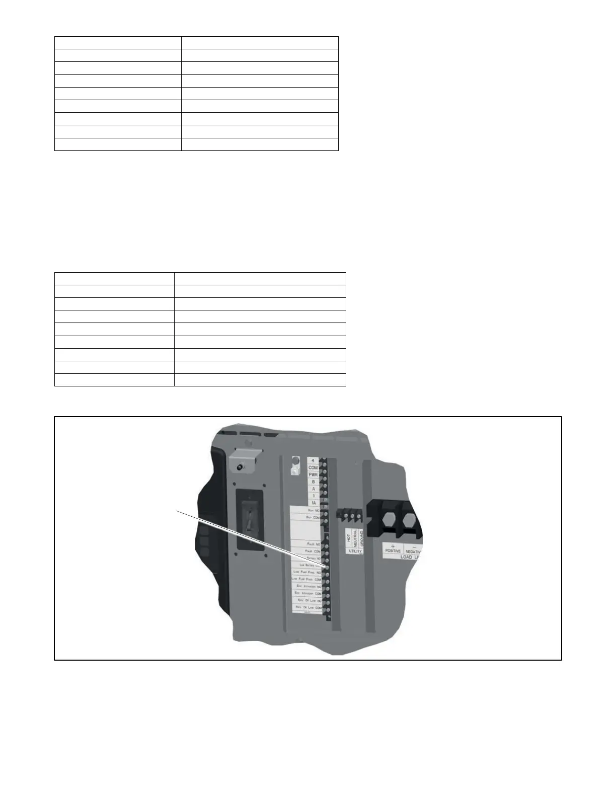
The outputs are factory-wired from the circuit board to terminal blocks in the customer connection area. Do not attempt to connect
directly to the interface board. The output contacts are normally open (NO); outputs close on activation. Connect customer
equipment to the outputs at the terminal blocks as shown in Figure 16.
Connection
Communications Kit
Input 1
Fuel Pressure
Input 2
Enclosure Intrusion Alarm
Output 1 (Relay 1)
Run
Output 2 (Relay 2)
Common Fault
Output 3 (Relay 3)
Battery Voltage
Output 4 (Relay 4)
Fuel Pressure Low Warning
Output 5 (Relay 5)
Enclosure Intrusion Alarm Warning
Output 6 (Relay 6)
Reserve Oil Empty (oil makeup kit required)
Figure 16 Communications Kit Factory Default Inputs and Outputs
Figure 17 Communications Kit Output Connections
Output connections
(6 outputs)
commConn
GM85956E

Other manuals for Kohler 6VSG

Questions and Answers:

Question and Answer IconNeed help?

Do you have a question about the Kohler 6VSG and is the answer not in the manual?

Kohler 6VSG Specifications

General IconGeneral
BrandKohler
Model6VSG
CategoryPortable Generator
LanguageEnglish

Related product manuals