Disassembly/Inspection and Service
108 62 690 05 Rev. EKohlerEngines.com
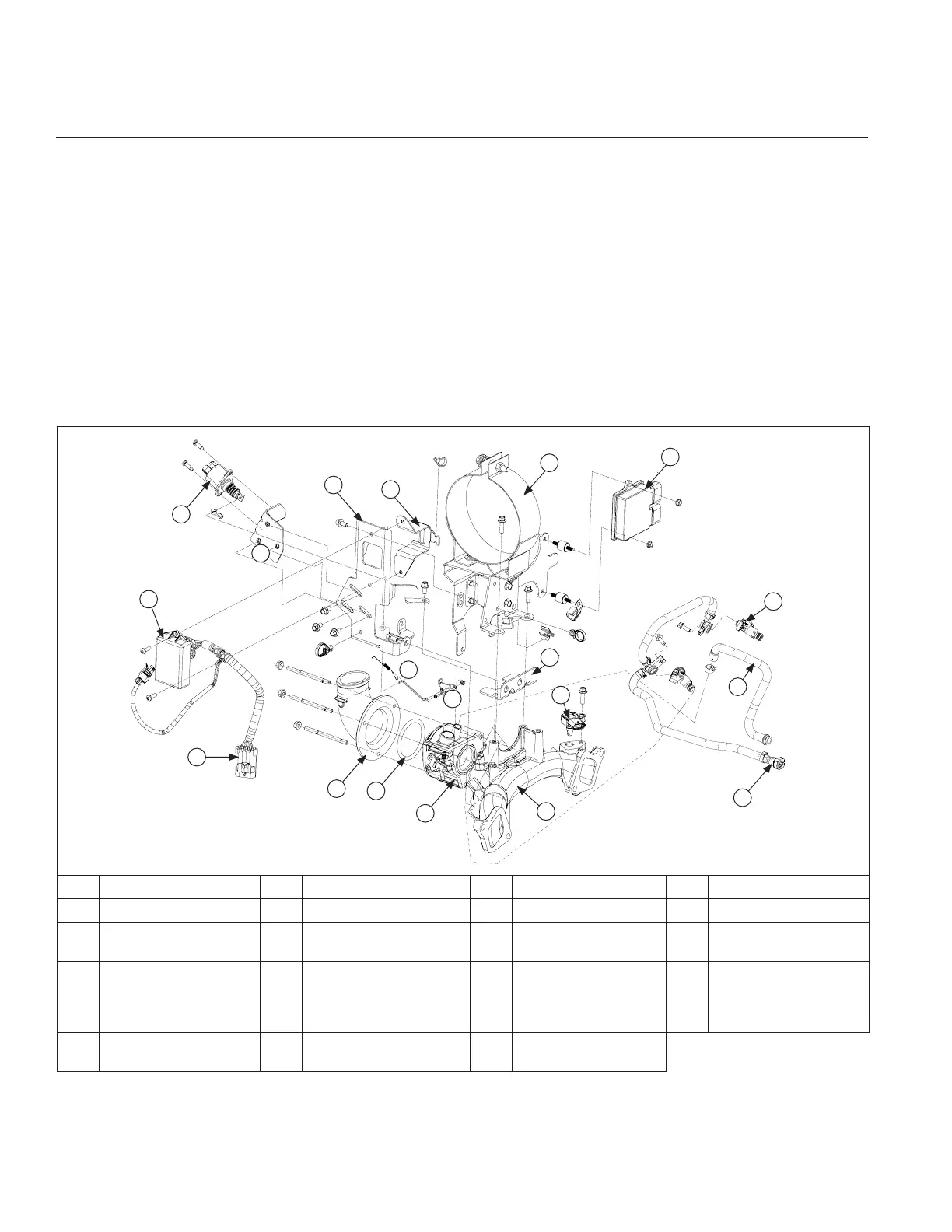
NEW UPDATED DESIGN Electronic Governor Intake and Throttle Body Assembly Components
A
B
C
D
E
G
H
I
J
K
Q
S
L
P
O
N
F
R
M
A Elbow B Elbow O-ring C Throttle Body D Intake Manifold
E Fuel Rail Assembly F Breather Hose G Injector H TMAP Sensor
I ECU J
Air Cleaner Bracket
Assembly
K Lifting Bracket L
Throttle Body Lever
Adapter
M Linkage & Spring N
4 Pin GCU to Main
Engine Harness
O
New Sealed (Bonded)
GCU Module
Wiring Harness
Assembly
P DLA Bracket
Q DLA R GCU Bracket S
GCU Wire Tie-Down
Bracket
Remove Sealed (Bonded) GCU Module Wiring Harness Assembly (FIELD INSTALLED UPDATED DESIGN
Electronic Governor)
1. Remove screws securing sealed (bonded) GCU module wiring harness assembly to GCU bracket.
2. Disconnect DLA wire.
3. Cut nylon tie straps retaining GCU wiring harness to GCU wire tie-down bracket.
4. Cut nylon tie strap retaining sheathing on speed input wire (red w/yellow stripe) and power wires.
5. Remove GCU ground wire and screw from air cleaner bracket assembly.
6. Slide sheathing down and disconnect wires from harness.
7. Slide power and speed input wires and sealed (bonded) GCU module wiring harness assembly upward from
engine; wires come out through square hole in GCU bracket.
8. Reverse procedure to install. Torque screws to 2.1 N·m (19 in. lb.).
 Loading...