Reassembly
118 62 690 05 Rev. EKohlerEngines.com
Install Hydraulic Lifters
NOTE: Hydraulic lifters should always be installed in
same position as they were disassembled.
Exhaust lifters are located on output shaft side
of engine while intake lifters are located on fan
side of engine. Cylinder numbers are embossed
on top of crankcase and each cylinder head.
1. Refer to Disassembly/Inspection and Service for
lifter preparation (bleed down) procedures.
2. Apply camshaft lubricant to bottom surface of each
lifter. Lubricate hydraulic lifters and lifter bores in
crankcase with engine oil. Do not prime lifters.
3. Note mark or tag identifying hydraulic lifters as either
intake or exhaust and cylinder 1 or cylinder 2. Install
hydraulic lifters into their appropriate location in
crankcase. Do not use a magnet.
Valve Stem Seals
These engines use valve stem seals on intake and
exhaust valves. Always use new seals whenever valves
are removed from cylinder head. Seals should also be
replaced if worn or damaged. Never reuse an old seal.
Assemble Cylinder Heads
Prior to installation, lubricate all components with engine
oil, paying particular attention to lip of valve stem seal,
valve stems, and valve guides. Install in order listed
below using a valve spring compressor.
● Intake and exhaust valves
● Valve spring retainers.
● Valve springs.
● Valve spring keepers.
● Valve stem seals.
● Guide plate (AVT only).
● Pivot studs (AVT only).
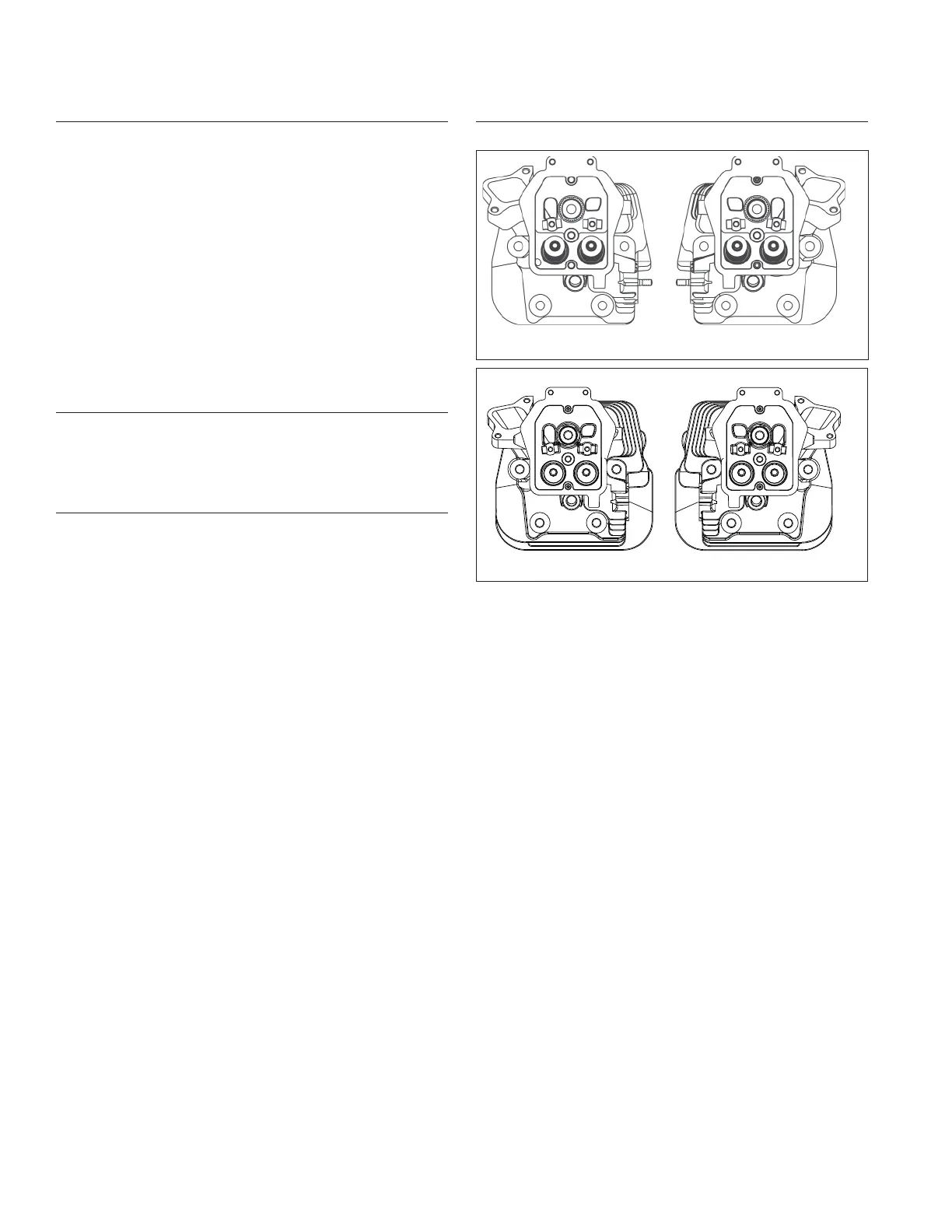
Install Cylinder Heads
Torque Sequence
12
2
2
4
4
5
5
3
3
1
1
NOTE: Match numbers embossed on cylinder heads
and crankcase.
1. Check to make sure there are no nicks or burrs on
sealing surfaces of cylinder head or crankcase.
2. Check dowel pins are in place in 2 lower locations,
and install a new cylinder head gasket, (printed side
up).
3. Install cylinder head. Make sure head is fl at on
gasket and dowel pins. Install a fl at washer on
screws in locations 1 and 3. Install spacer followed
by a fl at washer on screw in location 5. Start 5
screws.
4. Torque screws in 2 stages, fi rst to 23.7 N·m
(210 in. lb.), fi nally to 46.9 N·m (415 in. lb.) following
sequence shown.
5. Repeat procedure for opposite cylinder.
6. Make sure threads of pipe plugs for cylinder heads
are clean and dry. Install a plug into each cylinder
head above screw on location 2 and torque to
28.5 N·m (252 in. lb.).
12
2
4
5
13 31
54
2
 Loading...