6 — COMMISSIONING
Curtis AC F2-A, F4-A, F6-A Motor Controllers – FOS 4.5 – April 2022 Return to TOC
pg. 170
the opposite of these parameters’ default settings. e broken wire protection is by the controller
sensing the current ow from the pot wiper input through the potentiometer and into I/O Ground.
If either connection opens, it triggers the rottle Input fault (ash code 4-2).
3-Wire or 2-Wire throttle parameter setup
Wire the throttle corresponding to type as illustrated in Figures 12, 13, 36 or 37. For potentiometer
throttles, the potentiometer percentage (rottle Input) variable represents the throttle position as a
percentage of full throttle (100%). For throttle assemblies with validation switches or similar signals,
wire and program the validation signal(s) as per their type using the controller’s available switch or
analog inputs. Reference Figure 13 and Tables 8 and 9 for these available switch and analog inputs.
Be sure to include these additional signals in a VCL program as the means to integrate such throttle
validation signals into the controller application.
Note: When selecting a resistive throttle, the monitor item Analog 1 (analog_input_volts_1) reading
at pin 16 relates to the assigned potentiometer value and resistive validation, and as such, the
indicated voltage has no relevance to the throttle’s setup or diagnostics. e analog voltage monitor
value will cycle with the internal validation. Do not use the analog voltage for control purposes.
Voltage Throttle
When using a voltage source as a throttle, it is the responsibility of the OEM to provide appropriate
throttle fault detection. For ground-referenced 0–5 volt throttles, the controller will detect open
breaks (i.e., wire disconnect) in the Analog1 input (analog_input_volts_1), but it cannot provide
full throttle fault (valid throttle signal) protection. For tiller-handles providing a voltage signal, and
for tiller-handles providing a CANbus throttle command (i.e., VCL_rottle), throttle validation is the
responsibility of the vehicle OEM. It is recommended that throttle validation be handled within the
tiller-handle itself (i.e., as throttle assemblies oer).
To use a current source as a voltage throttle, add a resistor in parallel to the circuit to convert the
current source value to a voltage. Size the resistor to provide a 0–5V or 0–10V signal variation over
the full current range. It is the responsibility of the OEM to provide appropriate throttle fault detection
in these throttles as well. Reference the diagram in Figure 39, below.
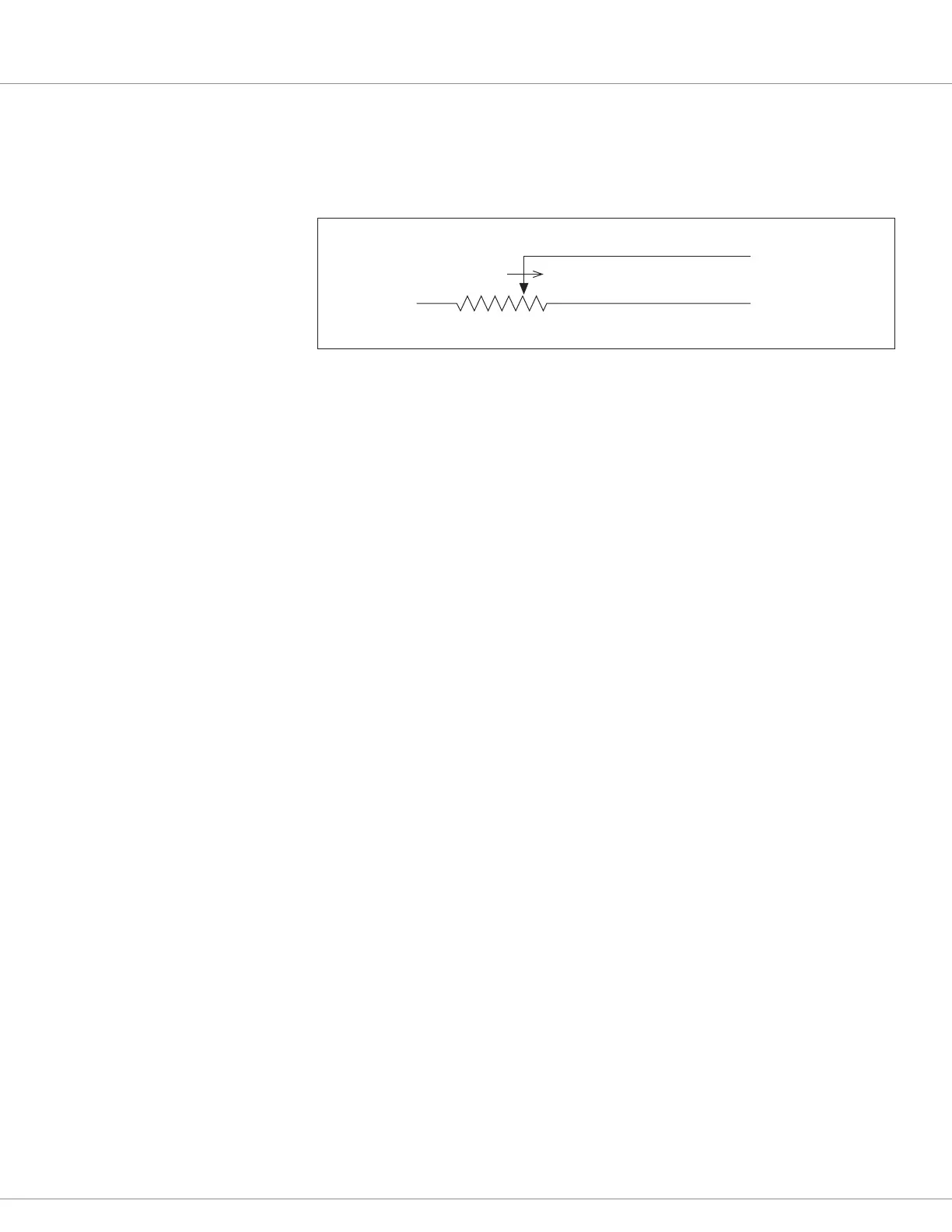
I/O Ground (Pin 7)
Pot 1 Wiper input (Pin 16)
5kΩ–0
FASTER
Figure 37
Wiring for 2-Wire
Potentiometer throttles
 Loading...