4 — PROGRAMMABLE PARAMETERS
Curtis AC F2-A, F4-A, F6-A Motor Controllers – FOS 4.5 – April 2022 Return to TOC
pg. 64
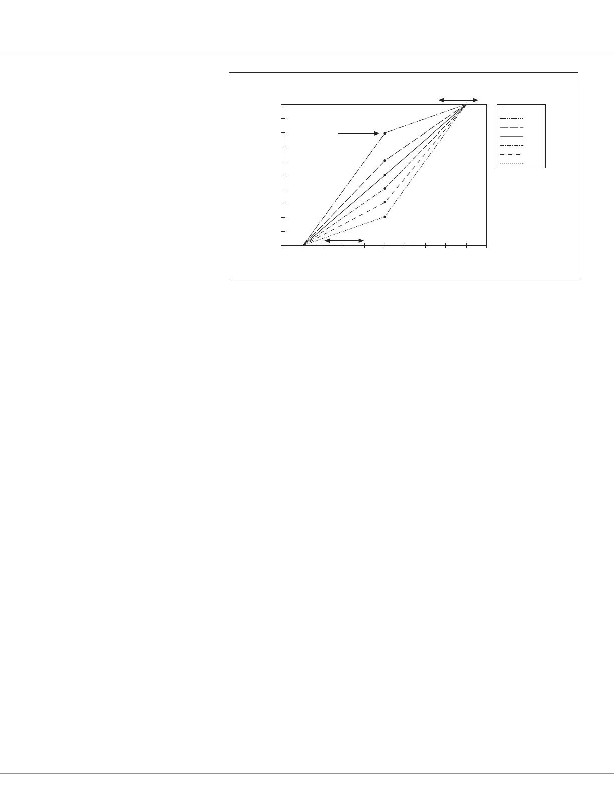
Max Input parameter
adjusts this endpoint.
80%
60%
50%
40%
30%
20%
MAP
THROTTLE INPUT PERCENT (%)
C ONTR OLL E R OUT PU T (percent)
Map Shape parameter determines the “knee”
in the output; this knee is
at an 80% Map Shape setting.
Min Input parameter
adjusts this endpoint (deadband)
10080604020 0
100
90
80
70
60
50
40
30
20
10
0
Figure 21
rottle Adjustments
Diagram
e eect of throttle
adjustment parameters.
Together these parameters
determine the controller’s
response to throttle demand
(in forward or reverse)
and to brake demand, if
applicable.
In the examples shown in
this gure,
Min Input = 10 %
Max Input = 95 %
Map Shape: six examples.
Figure 22 illustrates the throttle’s signal chain where the throttle parameters are applied. In addition
to these throttle-specic parameters, refer to the Controller Setup/Inputs menu (below) for the
selection of the throttle congurations. e default physical-throttle input is via Analog 1 Type
(Pot 1 Wiper, pin 16), which is an entry point for the throttle signal in Figure 22 (signal ow is le
to right). See Figure 13, the default wiring diagram, and Chapter 6, Commissioning, for systematic
throttle-option setup instructions.
Based upon the selection in the Inputs menu (i.e., voltage or potentiometer throttle) the throttle
will use two to three of the controller’s I/Os. For 5-volt voltage throttles, the +5V supply (pin 26)
and I/O Ground (Pin 18 or 7) are used to power the throttle, with the signal connected to Analog 1
(pin 16). Resistive 3-wire potentiometer throttles use the Pot 6 Supply (pin 15) and the I/O Ground
(pin 18 or 7) to set up the voltage-supply circuit with the potentiometer’s wiper (working as a voltage
divider) connected to the Pot 1 Wiper (pin 16). When using a 2-wire potentiometer throttle, connect
the potentiometer’s wiper to Pot 1 Wiper (pin 16) and one end to I/O Ground (pin 18 or 7). Leave the
other end/lead open, as the brake throttle in Figure 13 is a 2-wire input. When selecting these resistive
throttles, the monitor item Analog 1 (analog_input_volts_1) voltage reading at pin 16 undergoes
dynamic cycles verifying the external connections. is coupled to the assigned nominal resistance
value, results in the voltage reading having no relevance to the throttle signal. e motor direction
(Direction_Source) options are via the Forward/Reverse switch inputs or by Wigwag throttle. e
Single Switch option assigns forward as the default direction, with reverse its only input (hence, single
switch). Wigwag throttles are similar to voltage throttles, except their input voltage also determines
the motor direction. In all cases, the rst feedback in the throttle’s signal chain is the rottle_Pot_
Percent variable. Notice that the controller processes these inputs as a percentage, not as a voltage
(as noted above).
VCL can interface and modify the throttle signals at several points, from the voltage or potentiometer
input at pin 16 to the nal motor controller command. Use VCL to create unique throttle commands,
adjust parameters to provide Multimode operation, or modify the throttle command based on
steering angle, mast height, load, etc.
e throttle signal chains within the controller are sophisticated and exible. Before applying VCL
to modify these chains, it is important to understand the ramications of implementing changes.
With the physical throttle’s parameters set, the rottle_Pot_Percent variable passes to the rottle
Mapping block, which re-shapes the throttle signal magnitude and direction based on the various
rottle menu parameters and the directional inputs. When other Analog inputs are used for the
Quick Links:
Fig. 13 p.17
 Loading...