2 — INSTALLATION AND WIRING
Curtis AC F2-A, F4-A, F6-A Motor Controllers – FOS 4.5 – April 2022 Return to TOC
pg. 20
Low Current Connector Electrical Specifications
Digital (Switch) Inputs
e controllers oer exibility in conguring the digital inputs. For example, when congured as
switch inputs, the available inputs easily interface with user switches/buttons for the following:
• Interlock source.
• Vehicle directional input (forward and reverse).
• Forks li/lower operations.
• Emergency reverse (NO and NC paired inputs).
• Reach or height limit switches.
e switch inputs in the wiring diagrams illustrate connecting these to B+ (keyswitch) voltage. is
asserts the input to the “on” state. When the switch is open (not switched to B+), this is the non-
asserted, or “o” state. Table 8 lists the inputs’ specications. Notice that these are principally analog
inputs processing the applied voltage.
Virtual inputs
e input state is determined by processing the corresponding voltage from the analog input. ese
inputs have soware congurable High/Low thresholds. By default, these thresholds are set to
interface with Transistor-Transistor Logic (TTL) inputs; except for Input 1 & 13 (i.e. KSI and Coil
Supply), for which the threshold is set at the brown-out voltage for the controller. ese are reported
as either On or O. e virtual KSI monitor variable is Switch 20 (0x3339 0x00). e virtual Coil
Supply monitor variable is Coil_Supply_State (0x3C42 0x00).
Driver inputs
ese are digital inputs that are located on the same pins as the driver outputs. ese have a high
threshold of 8V and a low threshold of 1V. ese thresholds are as determined by the application’s
hardware/wiring conguration.
Generic inputs
ese digital inputs are not multiplexed with the analog input (such as a pot wiper) or the driver
outputs. ese have a high threshold of 4V (On) and a low threshold of 1V (O). ese thresholds
are as determined by the application’s hardware/wiring conguration.
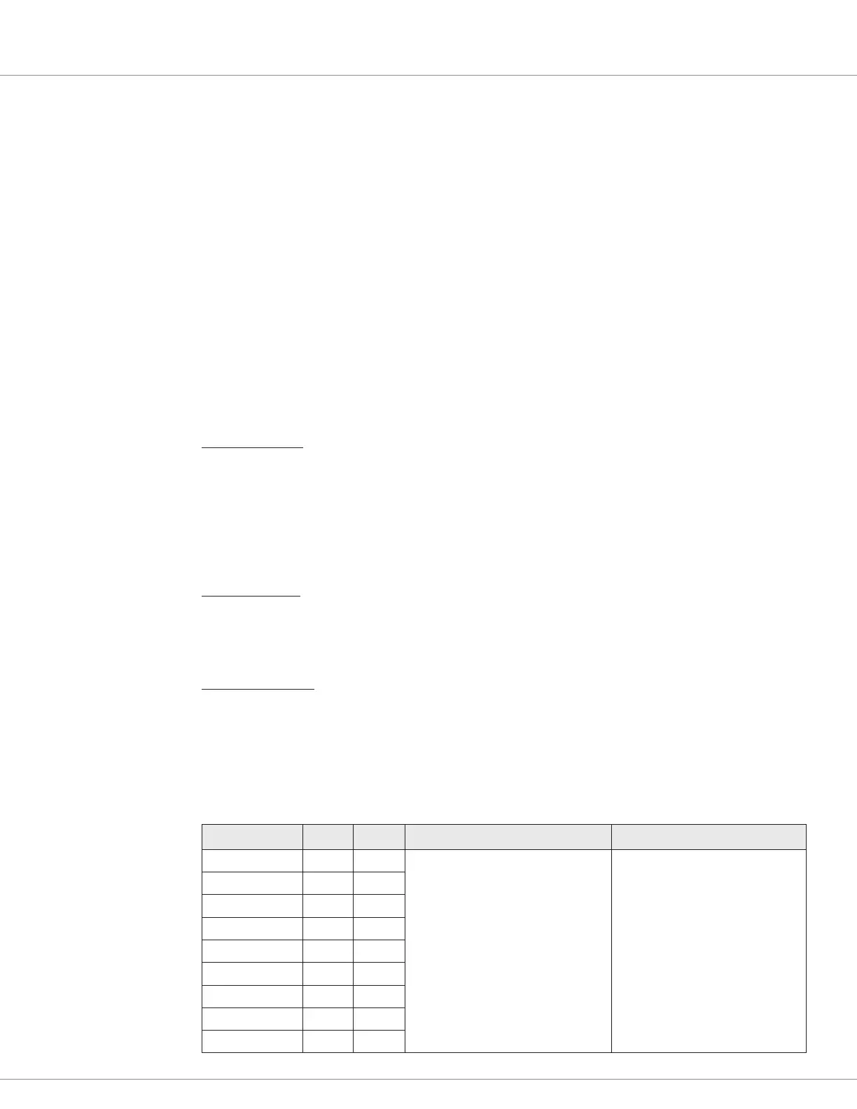
Table 8 Digital (Switch) Inputs Electrical Specifications
Signal Name 23-Pin 35-Pin Logic Threshold
1
Input Impedance
Switch 5 8 9 Rising edge = 4V max
Falling edge = 1V min
(Low / Off (pulled to B–)
24-36V models = 10kOhm ±10%
36-48V models = 18kOhm ±10%
Switch 7 14 22
Switch 8 15 33
Switch 9 n/a 24
Switch 10 n/a 10
Switch 11 19 11
Switch 12 21 12
Switch 13 22 14
Switch 14 n/a 25
 Loading...