6 — COMMISSIONING
Curtis AC F2-A, F4-A, F6-A Motor Controllers – FOS 4.5 – April 2022 Return to TOC
pg. 192
Lift & Lower Switch Inputs
is method uses the On/O switch inputs to command the hydraulic throttle (Li). Another On/
O switch commands the Lower operation, where a designated coil driver is either fully o (load
hold) or fully on (lowering). In this method, the hydraulic throttle and lower are non-variable inputs.
is is the illustrated “step function” ( ) in the gures 30 and 31 rottle/Switch Mapping. In this
example, reference Figures 13 and 29-31. e Li switch is Input 10 (pin 10). e Lower switch is
Input 11 (pin 11). A load hold valve is used.
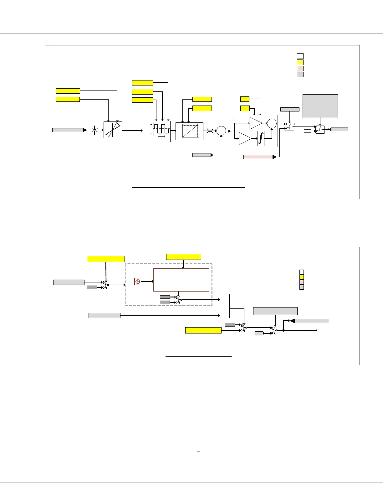
Proportional Valve Control
Conguration Parameter
VCL Function/Variable
Run-time variable
Function
Proportional Valve Driver
Dither for Valve Anti-Stick
+%Dither
-%Dither
Dither Period
+
-
Kp
Ki
+
+
PD Max Current
PD Dither Period
PD Dither Percent
PD Ki
1
0
Put_PWM(PWM5,xxxx)
1
0
0%
PD_Output
PD_Current
2A
0A
Current PI Controller
Generic Proportional
Driver Switch
Shut-Down
Shutdown_ PD
or
ThrottleInvalid
or
(CANopen Interlock== ON
and
CAN NMT State = Pre -Operational
)
PD_Enable== On
PD Kp
Current
%
100
0
Current Mapping
Min
Max
PD Max Current
PD Min Current
Lower_Throttle
Accel/Decel Rate
Processing
Driver#_Accel_Rate
100 %
0 %
Driver#_Decel_Rate
Figure 40
e Proportional Valve Signal Chain
Load Hold Driver
Load Hold Valve Hysteresis
Configura�on Parameter
VCL Func�on/Variable
Run-�me variable
Func�on
Load_Hold_Command
OFF
1
0
Valve kept closed after pump ON to allow for pre-pressurizing
Count Up
Timer
OR
1
0
0%
If any Hydraulic Faults Active
(Pump_HPD, HPD_Sequencing)
1
0
1
0
To Load Hold Driver
1
0
0
Tmr
Load_Hold_Enable-On_Lift
Pump_Throttle > 0%
Lower_Throttle > 5%
Load_Hold_Open_Delay
Load_Hold_Driver_Voltage
(Tmr > Load_Hold_Open_Delay) ||
(Load_Hold_Open_Delay = = 0)
Figure 41
e Load Hold Valve Signal Chain
Quick Links:
Fig. 13 p.17
Fig. 28 p.89
Fig. 29 p.90
Fig. 30 p.91
Fig. 31 p.91
 Loading...