2 — INSTALLATION AND WIRING
Curtis AC F2-A, F4-A, F6-A Motor Controllers – FOS 4.5 – April 2022 Return to TOC
pg. 24
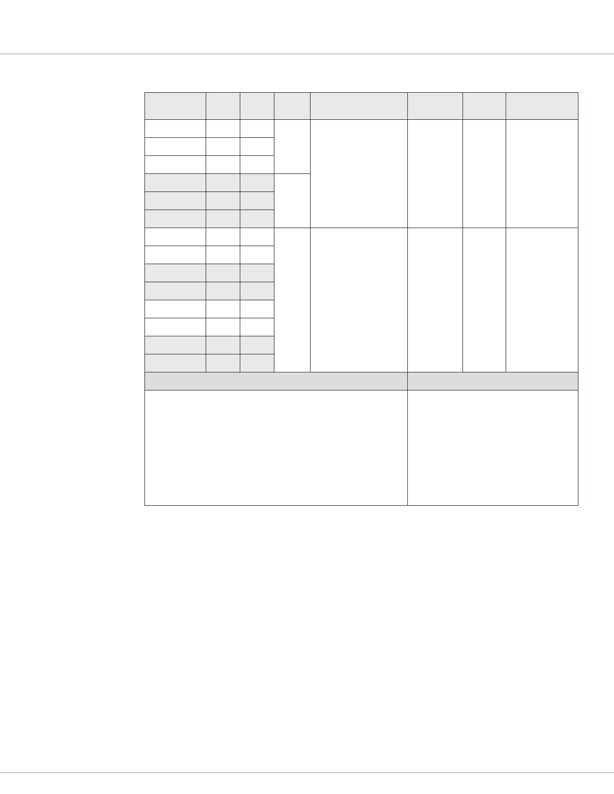
Table 10 Potentiometer Input/Configuration Electrical Specifications
Input
Signal Name
23-Pin 35-Pin Type
Pot Resistance Range
Available Current
Input
Impedance
Output
Voltage
Fault
Detection
Pot 6 Supply 10 15
3-Wire
1k – 10k Ω
3 mA supplied, Max.
20k Ω < 15V
Pot Wiper Open
Pot Resistance
Low
Pot Resistance
High
Circuit Failure
(internal)
Pot 1 Wiper 11 16
GND 12 18
1
Pot 19 Supply n/a 27
3-Wire
Pot 18 Wiper n/a 17
GND n/a 18
1
Pot 1 Input 11 16
2-Wire
1k – 10k Ω
3 mA supplied, Max.
20k Ω < 15V
Pot Wiper Open
Pot Resistance
High
Circuit Failure
(internal)
GND 12 18
1
Pot 6 Input n/a 15
GND n/a 18
1
Pot 18 Input n/a 17
GND n/a 18
1
Pot 19 Input n/a 27
GND n/a 18
1
VCL Functions VCL Monitor variables
Throttle_Pot_Percent
Throttle_Command
Throttle_Multiplier
Mapped_Throttle
Note: Similar variables exist for the brake,
if implemented.
Dual_Steer_Pot_Percent
Dual_Steer_Angle
1
Can also use pin 7 as a ground (GND).
PWM and Digital Drivers
Drivers 1 through 5 are low-side pulse-width-modulation (PWM) drivers. ese drivers are for
inductive loads such as contactor coils and electromagnetic brakes. ey can drive a resistive load if
the peak current is within the driver’s current rating. Use caution if the “load” is a RC-type circuit,
however, the high (capacitor) inrush current (currents exceeding 120%) will cause a Type 2 Driver
Overcurrent fault.
Each driver has a settable parameter (checks enable) to detect for an open and shorted coil (e.g.,
vehicle wiring related), and this parameter should be set to O if the driver is not used. e drivers
can withstand shorts to either B+ or B–. Always connect the drivers to the Coil Supply (pin 13)
which is the high side of the driver circuit (i.e., these low-side drivers “sink current” from the coil
supply, via the load). e Coil Supply provides an internal yback-diode for the inductive voltage-
spike protection.
 Loading...