132 Section 8 Component Testing and Adjustment TP-6356 4/12
Interface Circuit Board (C-354647 only). The DIP
switch SW1 on the interface circuit board must have the
settings shown in Figure 8-15.
ID Setting
A Open
B Closed
C Open
D Closed
Figure 8-15 DIP Switch SW1
If the engine rpm reading is incorrect or when there are
problems with disconnect or overspeed functions,
check the SW1 switch setting.
P27 DDEC ECM
Pin Description
A1 Output to DIB P4-1, low oil pressure (LOP) signal input,
wire 988 (not used on Series 60 engines)
A2 Output to DIB P4-5, pre-high engine temperature (PHET)
signal input, wire 555
F3 Output to DIB P4-3, high engine temperature (HET) signal
input, wire 499
K1 Output to DIB P4-6, speed sensor input (12 pulses per
revolution), wire 505
P4 DDEC Interface Circuit Board (DIB)
Pin Description
1 Input from DDEC P27-A1, LOP, wire 988
2
Input from generator set controller P1-7, engine run
(battery +), wire 70
3 Input from DDEC P27-F3, HET, wire 499
4 Shield, engine speed sensor, wire S1
5 Input from DDEC P27-A2, PHET, wire 555
6 Input from DDEC P27-K1, engine speed, wire 505
P5 DDEC Interface Circuit Board (DIB)
Pin Description
1 Not used
2 Output to generator set controller P1-9, speed sensor input
(2 pulses per revolution), wire 16
3 Ground from generator set controller P1-2, speed sensor
ground, wire 2
4 Not used
5 Not used
6 Battery positive from generator set controller P1-8, speed
sensor battery positive, wire 24
7 Output to generator set controller P1-22, low oil pressure
switch input, wire 13
8 Output to generator set controller P1-21, high engine
(coolant) temperature switch input, wire 34
9 Output to generator set controller P1-16,high engine
(coolant) temperature warning switch input, wire 40A
P1 Generator Set Controller Main Circuit Board
Pin Description
2 Ground to DIB P5-3, speed sensor ground, wire 2
7 Output to DIB P4-2, engine run (battery +), wire 70
8 Output to DIB P5-6, speed sensor battery positive, wire 24
9 Input from DIB P5-2, engine speed sensor input, wire 16
16 Input from DIB P5-9, high engine (coolant) temperature
switch input, wire 40A
21 Input from DIB P5-8, high engine (coolant) temperature
switch input, wire 34
22 Input from DIB P5-7, low oil pressure switch input, wire 13
8.11 Interface Circuit Board
GM24832
(Decision-Makerr 3+ and 550
Controllers)
Adapted from Service Bulletin SB-625 11/03.
8.11.1 Introduction
Use this section for controller troubleshooting and
inteface circuit board replacement. The interface circuit
board converts the engine speed sender signal to a
2-pulse output per engine revolution needed with some
controllers.
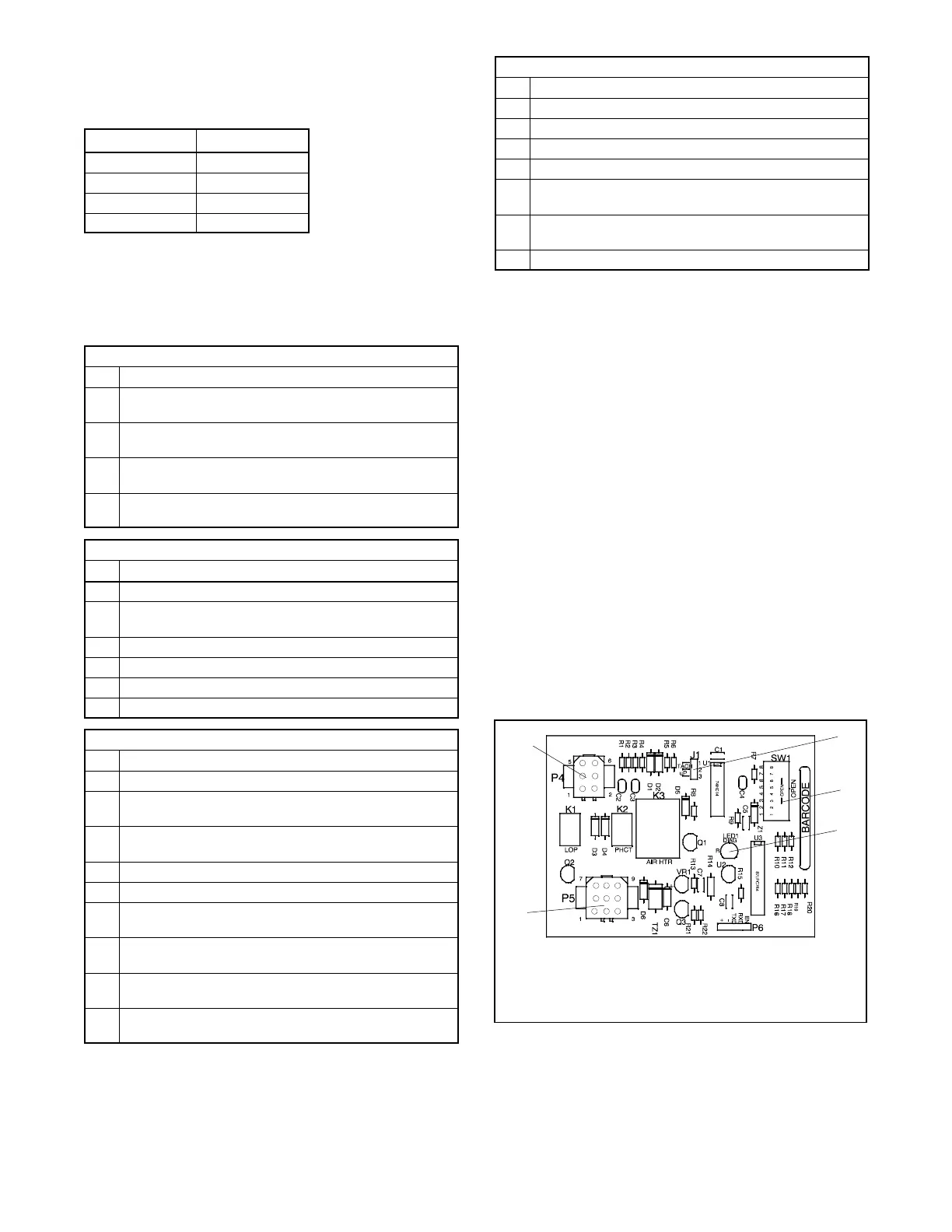
The interface circuit board GM24832 uses an 8-position
DIP switch to provide a 2-pulse output from flywheels
with a tooth count between 15 and 255. See
Figure 8-16 for the pulse converter circuit board. See
Figure 8-17 for circuit board mounting location in the
controller.
GM24832A-A
1. P4 connector
2. J1 jumper (programming shunt)
3. 8-Position DIP switch
4. Diagnostic LED1
5. P5 connector
2
1
5
3
4
Figure 8-16 Pulse Converter Circuit Board GM24832
 Loading...
