37Section 3 Decision-Makerr 3+ TroubleshootingTP-6356 4/12
Section 3 Decision -Makerr 3+ Troubleshooting
3.1 General Information
Use the following illustrations and text to troubleshoot
the controller. Figure 3-1 through Figure 3-9 show the
locations of controller components and connections.
Troubleshooting procedures provided in this section
and on the wiring diagrams may use active low and
active high terminology. A battery ground connection
energizes an active low circuit. A battery positive (+)
connection energizes an active high circuit.
Note: When a remote serial annunciator (RSA) is
connected to a Decision-Makerr 3+ controller, a
communication module circuit board is required.
Refer to Section 8.19, Communication Module
and Gauge Driver Circuit Board.
Before replacing the controller, remove all external
accessories and other electrical connections to verify
that these items are not the cause of the controller
problems. Verify that the accessories and connections
are functioning correctly before reconnecting them to
the new controller.
Electrical noise can affect the controller operation, refer
to Appendix F, Electrical Noise and Wiring Practices.
The controller receives input signals from several
senders/sensors that provide fault warnings and
shutdowns that can be tested for proper function.
Simulating these conditions may be helpful in
troubleshooting the generator set. Refer to Section
8.22, Fault Warning and Shutdown Testing.
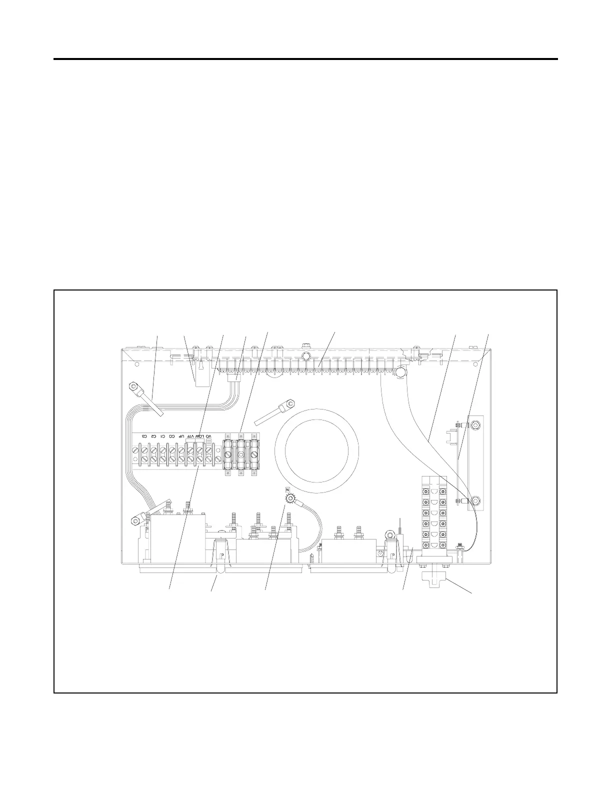
364451
1. Accessory wire guide loops
2. Controller fuses
3. Lamp selection jumper
4. Control panel harness connector (P2)
5. AC fuse terminal block (TB3)
6. Controller main circuit board
7. P3/P4 harness
8. Engine speed pulse counter interface circuit board
9. Selector switch
10. Indicator panel circuit board
11. Controller DC ground terminal
12. Panel lamps
13. CT/meter scale terminal block (TB2)
13
12 345 6 7 8
9101112
Figure 3-1 16-Light Controller Components
 Loading...
