153Section 8 Component Testing and AdjustmentTP-6356 4/12
8.22 Fault Warning and Shutdown
Testing
Adapted from Service Bulletin SB-616 9/11j, a
cumulative collection of generator set models.
Some generator set models with electronic control
modules (ECM) may limit or prohibit adjusting the
engine speed or testing the warning and shutdown
faults. This type of testing is typically required by the
NFPA 110 standard for emergency power supply
systems or by other governing agencies and is also
useful in troubleshooting the generator set engine and
controller. Figure 8-60 shows if the fault warning or fault
shutdown tests are feasible.
The engine ECM or other generator set controls may
impact the following shutdowns and warnings. The
letter (A or B) in parentheses identifies the fault category
in Figure 8-60.
D Overspeed (governor control) shutdown *
D Overcrank shutdown [
D High coolant temperature shutdown (A)
D High coolant temperature warning (A)
D Low coolant temperature warning (A)
D Low oil pressure shutdown (A)
D Low oil pressure warning (A)
D Battery charger fault warning (B)
D Low battery voltage warning (B)
D Low fuel (level or pressure) warning (B)
* Manually overspeed the engine if it is not ECM controlled.
[ To test overcrank (and cyclic engine cranking) on gas fueled
models, temporarily disconnect the ignition system. On
diesel-fueled models, temporarily disconnect the fuel injection
pump wire harness.
Use the information in Figure 8-62 through Figure 8-67
to test the engine sensor/switch faults during
troubleshooting of the generator set.
Test Method 1
Remove the sensor lead and ground the lead to the
engine block ground or connect a jumper wire from the
sensor terminal to the engine block ground.
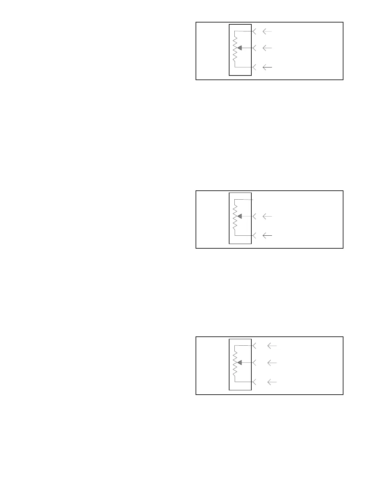
Test Method 2
Test faults using a 5 kOhm, 10-turn, 3-watt
potentiometer (part no. X-6136-36) and the illustration
shown in Figure 8-55. Before starting the generator set,
turn the potentiometer fully counterclockwise. While the
generator set is running, turn the potentiometer
clockwise until the unit shuts down.
SB616
B
C
A
RED
BLU/ORG, GRY/ORG, WHT
BLK
Wiring Harness
Connector Terminals
5kOhm
Pot.
Figure 8-55 Coolant Temp. and Oil Pressure Test
Test Method 3
Test coolant temperature faults using a 500 ohm,
10-turn, 3-watt potentiometer (part no. X-6136-37) and
the illustration shown in Figure 8-56. Turn
potentiometer fully counterclockwise before starting the
generator set. While the generator set is running, turn
the potentiometer clockwise until the unit shuts down.
The mating connector to the engine wiring harness
connector is a Packard Electrical Division part no.
12066016.
SB616
A
B
BLK, 461
PNK, TAN, 414, 464, 914
Wiring Harness
Connector Terminals
500 Ohm
Pot.
Figure 8-56 Coolant Temperature Test
Test Method 4
Test oil pressure faults using a 5 kOhm, 10-turn, 3-watt
potentiometer (part no. X-6136-36) and the illustration
shown in Figure 8-57. Before starting the generator set,
turn the potentiometer fully counterclockwise. While the
generator set is running, turn the potentiometer
clockwise until the unit shuts down.
SB616
A/1
B/2
C/4
BLK, 414, 452,
464, 914, B5--Pin 1
BRN, 467,
530, B5--Pin 2
GRY, 416, 911,
B5--Pin 4
Wiring
Harness
Connector
Terminals
5kOhm
Pot.
Figure 8-57 Oil Pressure Test
 Loading...
