200 Section 10 Governor Adjustments TP-6356 4/12
The Pause Chart button stops the chart recorder and
data file updates. Left click this button, which is now
named Continue, to activate the chart recorder.
Use the View Table button to return to the Table View
display mode. Be sure to open a new Data File before
returning to Table View if the data already collected
needs saving. The active Data File is automatically
reset each time the Chart View display mode becomes
active.
10.5.14 Installation Procedure
1. Determine the governor assembly part number
and engine model number. Before beginning the
programming procedure, the user must determine
the governor assembly part number and engine
model number. The selection of the correct
Parameter Text File later in this procedure depends
on knowing these numbers.
a. The governor assembly part number is
stamped on the replacement governor
included in the service kit. Knowing the service
kit number and using Figure 10-11 will also
provide the governor assembly part number.
b. The engine model number may be shown on
the engine nameplate attached to the
generator set engine block. Other sources for
finding the engine model number include the
respective generator set spec sheet and
documentation included with the generator set
sales invoice and/or warranty registration.
2. Connect the governor controller to the user-
supplied PC.
a. Place the generator set master switch in the
OFF/ RESET position.
b. Connect the supplied cable included in the kit
from the user-supplied PC 9-pin RS-232 serial
port to the governor controller RJ11 connector
(phone jack). See Figure 10-13.
3. Open the CD-ROM files.
The instructions provided assume you know how to
operate a PC.
a. Login to the user-supplied PC.
b. Load the CD-ROM in the PC.
c. Open the Readme.doc file and follow the
instructions described. Use the pst.help file as
needed.
d. Copy the PST, Setup, and Parameter Text files
to your PC hard drive.
e. Run the Setup file on your PC hard drive by
clicking File-Open-Setup Data and clicking
Run.
f. Copy the PST_CONFIG.mdb (MS
Accessdatabase) file and paste it in the same
folder as the PST file. The default folder is
ProgramFiles\Kohler\PST.
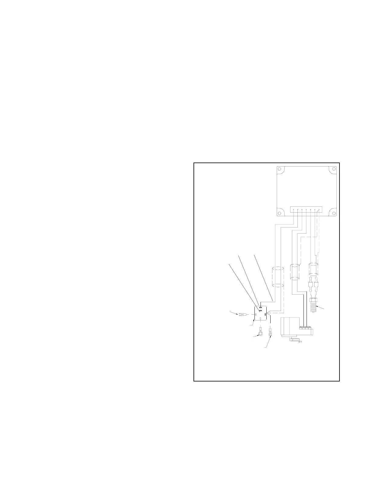
g. Energize the governor controller by moving the
white lead/70A from the normally open K5
contact to the normally closed K5 contact. See
Figure 10-16. Connecting to the normally
closed contact will energize the governor
controller without starting/running the
generator set.
GM17725B-E
SW70--1624--5722
SW7N--1624--9722
CONNECT TO 70 ON SAFEGUARD
BREAKER TERMINAL STRIP
BLACK
CONNECT TO 7N ON SAFEGUARD
BREAKER TERMINAL STRIP
SWP--1450--5716
CONNECT TO CRANKING
SOLENOID (BATTERY (+)
70
P
7N
RELAY
WHITE
ACTUATOR
MAG PICK--UP
BLACK
UNINSULATED
WHITE
UNINSULATED
BLACK
WHITE
MPU--
MPU--SHLD
ACT --
ACT+
BAT--
BAT+
MPU+
UNINSULATED
WHITE
BLACK
86 85
87A
87
K5
NO
NC
30
C
1. Normally closed K5 contact
2. Normally open K5 contact
3. White lead/70A
1
2
3
Figure 10-16 Energizing the Governor Controller
(non-load share model shown)
 Loading...
