50 Section 3 Decision-Makerr 3+ Troubleshooting TP-6356 4/12
Disabling the generator set. Accidental starting can
cause severe injury or death. Before working on the
generator set or connected equipment, disable the generator
set as follows: (1) Move the generator set master switch to the
OFF position. (2) Disconnect the power to the battery charger.
(3) Remove the battery cables, negative (--) lead first.
Reconnect the negative (--) lead last when reconnecting the
battery. Follow these precautions to prevent starting of the
generator set by an automatic transfer switch, remote
start/stop switch, or engine start command from a remote
computer.
3.5.1 Fuses
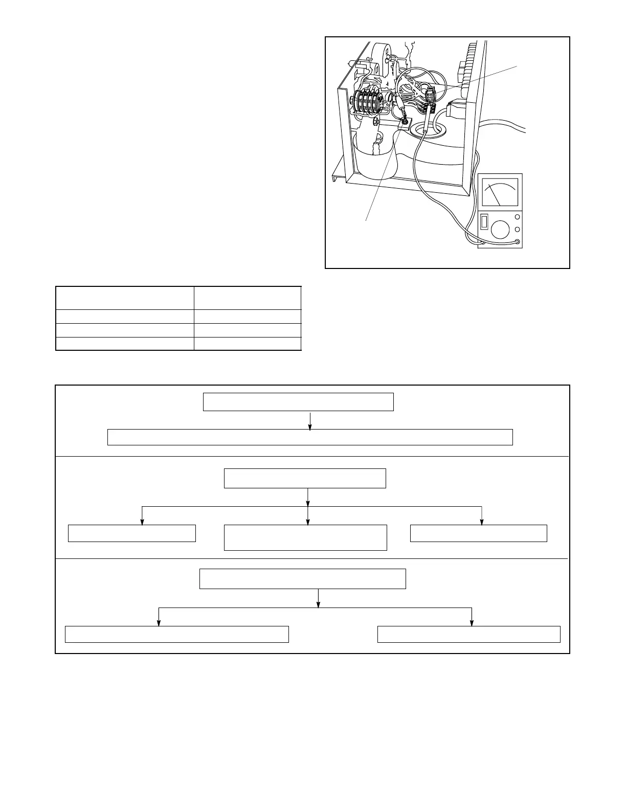
To quickly check the condition of the components
mentioned in the following flowcharts, use an ohmmeter
to measure resistance between designated terminal
and ground. See Figure 3-16 and Figure 3-17. With
ohmmeter on R x 1 scale, a reading of less than 1 ohm
(continuity) indicates a potentially defective component.
Isolate the defective component and repair or replace.
Component
Connect between ground
and terminal:
Engine Gauges Connector P2, pin 1
Crank (K2 Relay) Circuit Connector P1, pin 1
Fuel/ignition Circuit Connector P1, pin 7
Figure 3-16 P1 and P2 Connections
3-187
Ω
1
2
1. Ground connection
2. P2 connection
Figure 3-17 Checking P1 and P2 Connections
Figure 3-18 lists the possible causes of blown controller
fuses F1, F2, and F3. Replace blown fuses and resume
operation. If the fuse blows again, use the chart to
identify the faulty component(s).
Blown F1 fuse (remote annunciator: 3 amp)
Blown F2 fuse (controller: 3 amp)
Battery connections reversed Shorted DC supply to indicator panel
circuit board
Shorted controller circuit board
Blown F3 fuse (engine and accessories: 15 amp)
Defective engine electrical (wire 70) components
Defective panel lamps or engine gauges
Defective dry contact, kit, audio/visual alarm kit, and other accessories connected to TB1-42A
Figure 3-18 Checking Fuses F1, F2, and F3
 Loading...
