135Section 8 Component Testing and AdjustmentTP-6356 4/12
8.12 Low Fuel Pressure (Vacuum)
Switches
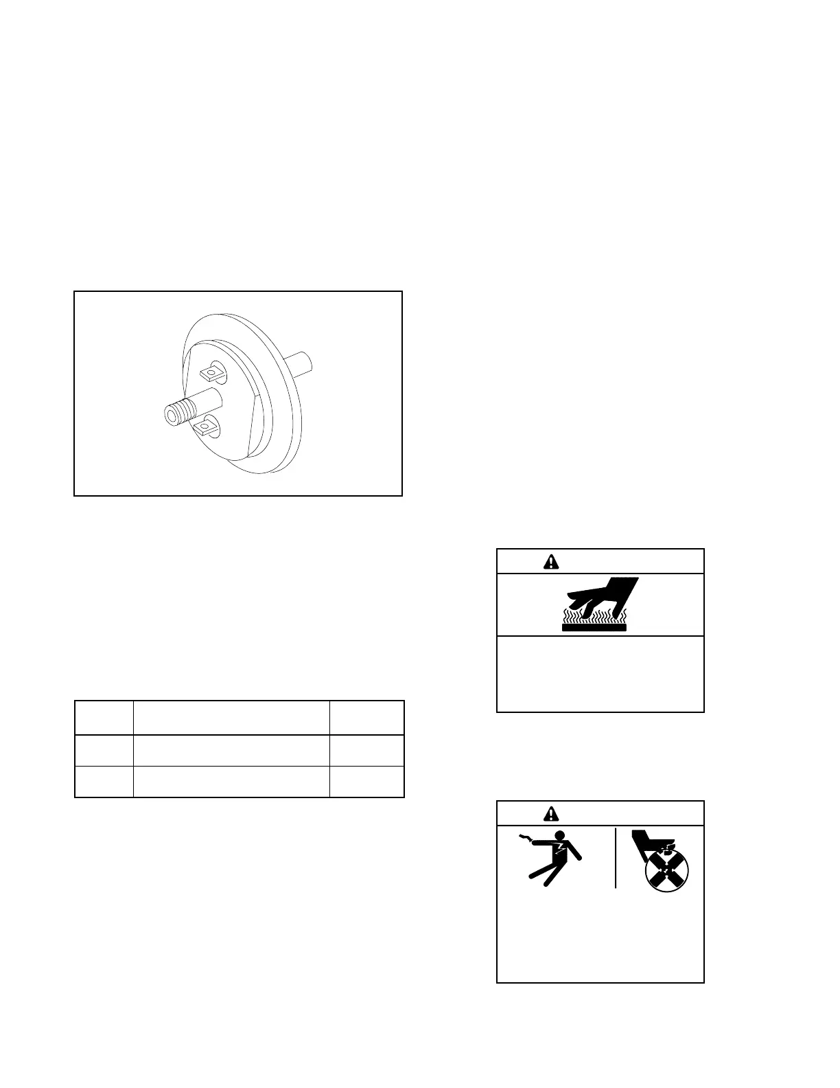
The low fuel pressure (vacuum) switch (see
Figure 8-23) is used on selected gas models to:
D Signal a low fuel warning (lead 63)
D Trigger the secondary fuel source on dual fuel gas
systems with automatic changeover options.
D Signal a low fuel shutdown as an immediate auxiliary
shutdown on the 125 kW with turbocharged 8.1 L GM
engine.
TP-5353-7
Figure 8-23 Low Fuel Pressure (Vacuum) Switch
Use an ohmmeter and check for continuity across the
two terminals. The circuit opens when a vacuum source
indicated in Figure 8-24 is applied. These switches
incorporate a diaphragm type sensing device. When
testing, apply the vacuum for several minutes to help
determine if the switch has a leaking diaphragm
(internal leak) or a leaking canister (external leak).
Replace the switch if any leakage is found or if the switch
fails the continuity test.
Part
Number
Switch Description
Vacuum,
kPa (psi)
287387
Fuel Pressure Switch
(Automatic Changeover Option)
0.87--1.0
(0.13--0.14)
345207
Low Fuel Pressure Warning
(Low Fuel)
1.1--1.2
(0.16--0.18)
Figure 8-24 Low Fuel Pressure (Vacuum) Switch
8.13 Low Water Level
8.13.1 2-Wire Sender
Function
The 2-wire low water level (LWL) sender is a
resistance/temperature device. Lead 31A from the
controller provides a 12 VDC supply to the sender. The
controller provides 12 VDC on both 12-volt and 24-volt
engine electrical systems. The 12 volt supply heats the
center electrode on the sender. The sender
temperature remains low when immersed in coolant
while the resistance to ground is high. The resistance to
ground decreases when the sender is out of contact with
coolant and the center electrode temperature rises.
Low sender resistance raises the current draw which
lowers the voltage to approximately 7 VDC on lead 31A.
A comparator circuit on the controller circuit board
senses the voltage drop and sends a signal to the
controller logic for an auxiliary fault shutdown after
completing the time delay.
Testing
Use the following test procedure for the 2-wire low water
level sender while the generator set operates. Lead 31A
must remain connected to the sender during the test.
Hot engine and exhaust system.
Can cause severe injury or death.
Do not work on the generator set until
it cools.
WARNING
Servicing the exhaust system. Hot parts can cause
severe injury or death. Do not touch hot engine parts. The
engine and exhaust system components become extremely
hot during operation.
Hazardous voltage.
Can cause severe injury or death.
Operate the generator set only when
all guards and electrical enclosures
areinplace.
Moving parts.
WARNING
 Loading...
