TP-7091 4/23 41
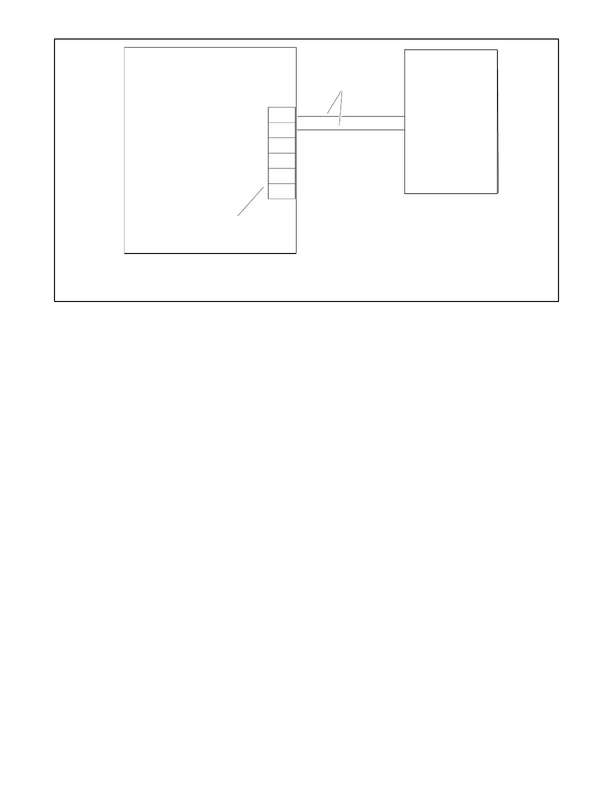
1. Generator Set Terminal Block. Check the decal on the generator set for terminal block connections.
2. Engine start leads 3 and 4. See the ATS manual for cable size specifications.
Figure 29 Engine Start Connections with Transfer Switch Models other than Model RXT
3.3.3 System Connections with Accessory Modules
See Figure 30 through Figure 34 for connection options to RBUS accessory modules. Note the cable shield connections shown
in Figure 30.
Note:
Refer to the installation instructions provided with the automatic paralleling module (APM) for RBUS connections to the APM.
The maximum cable length depends on the number of RBUS modules connected. See the Communications Cable
Specifications section for the maximum cable lengths with 1, to 4 modules per cable run.
Note:
A model RXT transfer switch with combined interface/ load management board acts as two RBUS modules: one RXT transfer
switch and one load management device.
Power Relay Modules are not RBUS modules and do not add to the number of modules when determining the maximum cable
length.
 Loading...